| CHAPTER VIII.
THE REAL FLYING MACHINE. Flying Machines: Construction and Operation: A Practical Book Which Shows, in Illustrations, Working Plans and Text, How to Build and Navigate the Modern Airship. | ||
8. CHAPTER VIII.
THE REAL FLYING MACHINE.
We will now assume that you have become proficient enough to warrant
an attempt at the construction of a real flying machine—one that will
not only remain suspended in the air at the will of the operator, but
make respectable progress in whatever direction he may desire
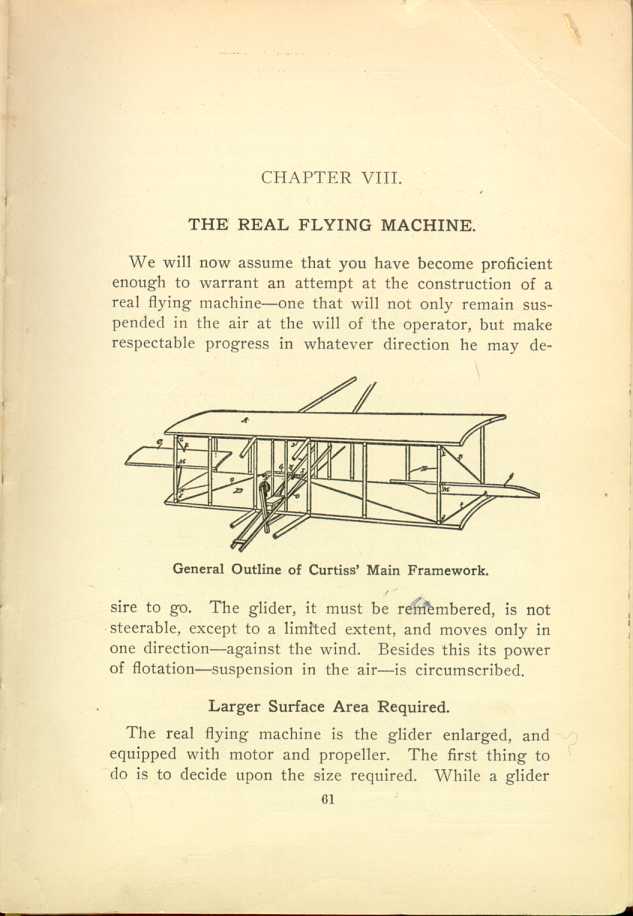
General Outline of Curtiss' Main Framework.
[Description: Black and white illustration: Diagram of aeroplane.]
Larger Surface Area Required.
The real flying machine is the glider enlarged, and equipped with motor and propeller. The first thing to do is to decide upon the size required. While a glider
Some Practical Examples.
The Wrights used a biplane 41 feet in spread, and 6 1/2 ft. deep. This, for the two planes, gives a total surface area of 538 square feet, inclusive of auxiliary planes. This sustains the engine equipment, operator, etc., a total weight officially announced at 1,070 pounds. It shows a lifting capacity of about two pounds to the square foot of plane surface, as against a lifting capacity of about 1/2 pound per square foot of plane surface for the 20-foot glider. This same Wright machine is also reported to have made a successful flight, carrying a total load of 1,100 pounds, which would be over two pounds for each square foot of surface area, which, with auxiliary planes, is 538 square feet.
To attain the same results in a monoplane, the single surface would have to be 60 feet in spread and 9 feet deep. But, while this is the mathematical rule, Bleriot has demonstrated that it does not always hold good. On his record-breaking trip across the English channel, July 25th, 1909, the Frenchman was carried in a monoplane 24 1/2 feet in spread, and with a total sustaining surface of 150 1/2 square feet. The total weight of the outfit, including machine, operator and fuel sufficient for a three-hour run, was only 660 pounds. With an engine of (nominally) 25 horsepower the distance of 21 miles was covered in 37 minutes.
Which is the Best?
Right here an established mathematical quantity is involved. A small
plane surface offers less resistance to the air than a large one and
consequently can attain a higher rate of speed. As explained further on
in this chapter speed is an important factor in the matter of
weight-sustaining capacity. A machine that travels one-third faster than
another can get along with one-half the
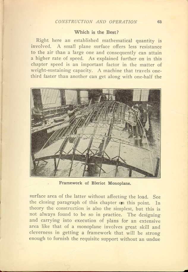
Framework of Bleriot Monoplane.
[Description: Black and white photograph: Men working on aeroplane frame.]
Proper Sizes For Frame.
Allowing that the biplane form is selected the construction may be practically identical with that of the 20-foot glider described in Chapter V., except as to size and elimination of the armpieces. In size the surface planes should be about twice as large as those of the 20-foot glider, viz: 40 feet spread instead of 20, and 6 feet deep instead of 3. The horizontal beams, struts, stanchions, ribs, etc., should also be increased in size proportionately.
While care in the selection of clear, straight-grained timber is important in the glider, it is still more important in the construction of a motor-equipped flying machine as the strain on the various parts will be much greater.
How to Splice Timbers.
It is practically certain that you will have to resort to splicing the horizontal beams as it will be difficult, if not impossible, to find 40-foot pieces of timber totally free from knots and worm holes, and of straight grain.
If splicing is necessary select two good 20-foot pieces, 3 inches wide and 1 1/2 inches thick, and one 10-foot long, of the same thickness and width. Plane off the bottom sides of the 10-foot strip, beginning about two feet back from each end, and taper them so the strip will be about 3/4 inch thick at the extreme ends. Lay the two 20-foot beams end to end, and under the joint thus made place the 10-foot strip, with the planed-off ends downward. The joint of the 20-foot pieces should be directly in the center of the 10-foot piece. Bore ten holes (with a 1/4-inch
Splicing with Metal Sleeves.
An even better way of making a splice is by tonguing and grooving the
ends of the frame pieces and enclosing
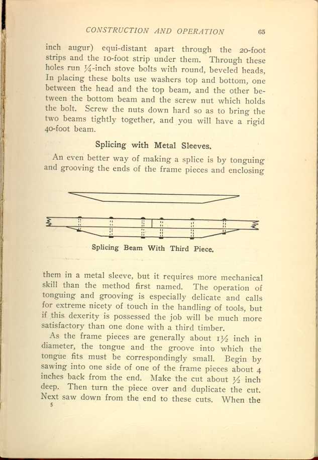
Splicing Beam With Third Piece.
[Description: Black and white illustration: Splicing beam.]
As the frame pieces are generally about 1 1/2 inch in diameter, the tongue and the groove into which the tongue fits must be correspondingly small. Begin by sawing into one side of one of the frame pieces about 4 inches back from the end. Make the cut about 1/2 inch deep. Then turn the piece over and duplicate the cut. Next saw down from the end to these cuts. When the
Joining the Two Pieces.
Take a thin metal sleeve—this is merely a hollow tube of aluminum or
brass open at each end—8 inches long, and slip it over either the
tongued or grooved end of one of the frame timbers. It is well to have
the sleeve fit
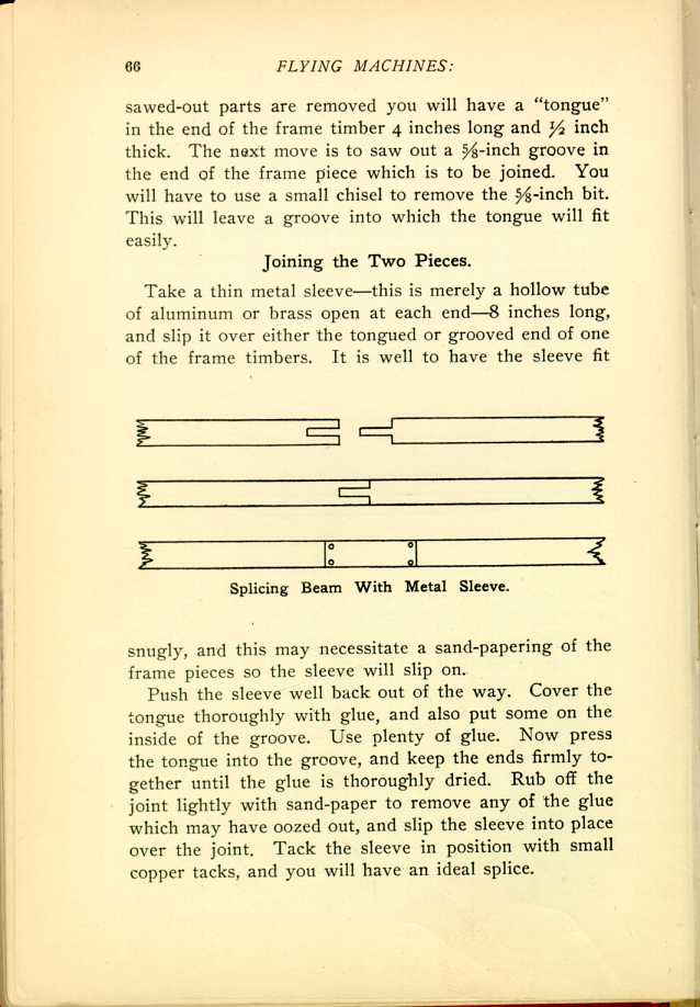
Splicing Beam With Metal Sleeve.
[Description: Black and white illustration: Three-part diagram of splicing
beam joined.]
Push the sleeve well back out of the way. Cover the tongue thoroughly with glue, and also put some on the inside of the groove. Use plenty of glue. Now press the tongue into the groove, and keep the ends firmly together until the glue is thoroughly dried. Rub off the joint lightly with sand-paper to remove any of the glue which may have oozed out, and slip the sleeve into place over the joint. Tack the sleeve in position with small copper tacks, and you will have an ideal splice.
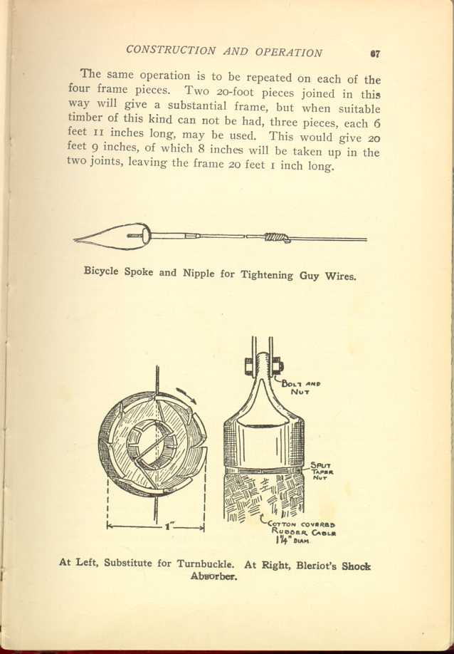
The same operation is to be repeated on each of the four frame pieces. Two 20-foot pieces joined in this way will give a substantial frame, but when suitable timber of this kind can not be had, three pieces, each 6 feet 11 inches long, may be used. This would give 20 feet 9 inches, of which 8 inches will be taken up in the two joints, leaving the frame 20 feet 1 inch long.

Installation of Motor.
Next comes the installation of the motor. The kinds and efficiency of the various types are described in the following chapter (IX). All we are interested in at this point is the manner of installation. This varies according to the personal ideas of the aviator. Thus one man puts his motor in the front of his machine, another places it in the center, and still another finds the rear of the frame the best. All get good results, the comparative advantages of which it is difficult to estimate. Where one man, as already explained, flies faster than another, the one beaten from the speed standpoint has an advantage in the matter of carrying weight, etc.
The ideas of various well-known aviators as to the correct placing of motors may be had from the following:
Wrights—In rear of machine and to one side.
Curtiss—Well to rear, about midway between upper and lower planes.
Raich—In rear, above the center.
Brauner-Smith—In exact center of machine.
Van Anden—In center.
Herring-Burgess—Directly behind operator.
Voisin—In rear, and on lower plane.
Bleriot—In front.
R. E. P.—In front.
The One Chief Object.
An even distribution of the load so as to assist in maintaining the equilibrium of the machine, should be the one chief object in deciding upon the location of the motor. It matters little what particular spot is selected so long as the weight does not tend to overbalance the machine, or to "throw it off an even keel." It is just like loading a vessel, an operation in which the expert
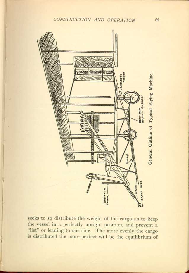
General Outline of Typical Flying Machine.
[Description: Black and white illustration: Diagram of flying machine.]Shape of Machine a Factor.
In placing the motor you must be governed largely by the shape and construction of the flying machine frame. If the bulk of the weight of the machine and auxiliaries is toward the rear, then the natural location for the motor will be well to the front so as to counterbalance the excess in rear weight. In the same way if the preponderance of the weight is forward, then the motor should be placed back of the center.
As the propeller blade is really an integral part of the motor, the latter being useless without it, its placing naturally depends upon the location selected for the motor.
Rudders and Auxiliary Planes.
Here again there is great diversity of opinion among aviators as to size, location and form. The striking difference of ideas in this respect is well illustrated in the choice made by prominent makers as follows:
Voisin—horizontal rudder, with two wing-like planes, in front; box-like longitudinal stability plane in rear, inside of which is a vertical rudder.
Wright—large biplane horizontal rudder in front at considerable distance—about 10 feet—from the main planes; vertical biplane rudder in rear; ends of upper
Curtiss—horizontal biplane rudder, with vertical damping plane
between the rudder planes about 10 feet in front of main planes;
vertical rudder in rear; stabilizing planes at each end of upper main
plane.
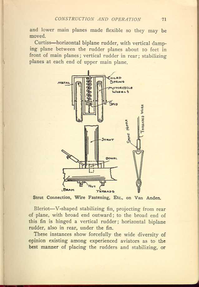
Strut Connection, Wire Fastening, Etc., on Van Anden.
[Description: Black and white illustration: diagram of struts and wires.]
Bleriot—V-shaped stabilizing fin, projecting from rear of plane, with broad end outward; to the broad end of this fin is hinged a vertical rudder; horizontal biplane rudder, also in rear, under the fin.
These instances show forcefully the wide diversity of opinion existing among experienced aviators as to the best manner of placing the rudders and stabilizing, or
Rudder and Auxiliary Construction.
The material used in the construction of the rudders and auxiliary planes is the same as that used in the main planes—spruce for the framework and some kind of rubberized or varnished cloth for the covering. The frames are joined and wired in exactly the same manner as the frames of the main planes, the purpose being to secure the same strength and rigidity. Dimensions of the various parts depend upon the plan adopted and the size of the main plane.
No details as to exact dimensions of these rudders and auxiliary planes are obtainable. The various builders, while willing enough to supply data as to the general measurements, weight, power, etc., of their machines, appear to have overlooked the details of the auxiliary parts, thinking, perhaps, that these were of no particular import to the general public. In the Wright machine, the rear horizontal and front vertical rudders may be set down as being about one-quarter (probably a little less) the size of the main supporting planes.
Arrangement of Alighting Gear.
Most modern machines are equipped with an alighting gear, which not only serves to protect the machine and aviator from shock or injury in touching the ground, but also aids in getting under headway. All the leading makes, with the exception of the Wright, are furnished with a frame carrying from two to five pneumatic rubber-tired bicycle wheels. In the Curtiss and Voisin machines one wheel is placed in front and two in the rear. In the Bleriot and other prominent machines the
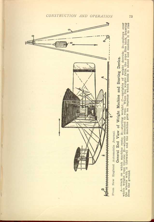
From New England Automobile Journal.
General End View of Wright Machine and Starting Device.
A—track on which machine rests; B—starting weight; C—uprights of
weight derrick; D—pulleys over which weight rope travels; E—wheels
attached to rope. When the weight falls, the rope flies back, drawing
the wheels with it (forward) and the machine gets an impetus which
sends it ahead and enables it to rise from the ground.
[Description: Black and white illustration: Diagram of aeroplane and
starting device.]
In place of wheels the Wright machine is equipped with a skid-like device consisting of two long beams attached to the lower plane by stanchions and curving up far in front, so as to act as supports to the horizontal rudder.
Why Wood Is Favored.
A frequently asked question is: "Why is not aluminum, or some similar metal, substituted for wood." Wood, particularly spruce, is preferred because, weight considered, it is much stronger than aluminum, and this is the lightest of all metals. In this connection the following table will be of interest:
| Material | Weight per cubic foot in lbs. | Tensile Strength per sq. inch in lbs. | Compressive Strength per sq. inch in lbs. |
| Spruce | 25 | 8,000 | 5,000 |
| Aluminum | 162 | 16,000 | ...... |
| Brass (sheet) | 510 | 23,000 | 12,000 |
| Steel (tool) | 490 | 100,000 | 40,000 |
| Copper (sheet) | 548 | 30,000 | 40,000 |
As extreme lightness, combined with strength, especially tensile strength, is the great essential in flying-machine construction, it can be readily seen that the use of metal, even aluminum, for the framework, is prohibited by its weight. While aluminum has double the strength of spruce wood it is vastly heavier, and thus the advantage it has in strength is overbalanced many times by its weight. The specific gravity of aluminum is 2.50; that of spruce is only 0.403.
Things to Be Considered.
In laying out plans for a flying machine there are five important points which should be settled upon before the actual work of construction is started. These are:
First—Approximate weight of the machine when finished and equipped.
Second—Area of the supporting surface required.
Third—Amount of power that will be necessary to secure the desired speed and lifting capacity.
Fourth—Exact dimensions of the main framework
and of the auxiliary parts.
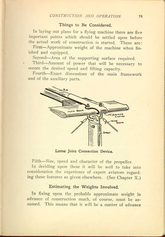
Loose Joint Connection Device.
[Description: Black and white illustration: Diagram of connection device.]
Fifth—Size, speed and character of the propeller.
In deciding upon these it will be well to take into consideration the experience of expert aviators regarding these features as given elsewhere. (See Chapter X.)
Estimating the Weights Involved.
In fixing upon the probable approximate weight in advance of construction much, of course, must be assumed. This means that it will be a matter of advance
What the Novice Must Avoid.
This does not mean, however, that it will be safe to follow these weights exactly in construction, but that they will serve merely as a basis to start from. Because an expert can turn out a machine, thoroughly equipped, of 850 pounds weight, it does not follow that a novice can do the same thing. The expert's work is the result of years of experience, and he has learned how to construct frames and motor plants of the utmost lightness and strength.
It will be safer for the novice to assume that he can not duplicate the work of such men as Wright and Curtiss without adding materially to the gross weight of the framework and equipment minus passengers.
How to Distribute the Weight.
Let us take 1,030 pounds as the net weight of the machine as against the same average in the Wright and Curtiss machines. Now comes the question of distributing this weight between the framework, motor, and other equipment. As a general proposition the framework should weigh about twice as much as the complete power plant (this is for amateur work).
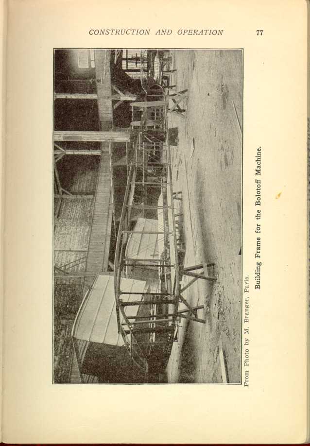
From Photo by M. Branger, Paris.
Building Frame for the Bolotoff Machine.
[Description: Black and white photograph: Framework of an aeroplane.]
The word "framework" indicates not only the wooden frames of the main planes, auxiliary planes, rudders, etc., but the cloth coverings as well—everything in fact except the engine and propeller.
On the basis named the framework would weigh 686 pounds, and the power plant 344. These figures are liberal, and the results desired may be obtained well within them as the novice will learn as he makes progress in the work.
Figuring on Surface Area.
It was Prof. Langley who first brought into prominence in connection with flying machine construction the mathematical principle that the larger the object the smaller may be the relative area of support. As explained in Chapter XIII, there are mechanical limits as to size which it is not practical to exceed, but the main principle remains in effect.
Take two aeroplanes of marked difference in area of surface. The larger will, as a rule, sustain a greater weight in relative proportion to its area than the smaller one, and do the work with less relative horsepower. As a general thing well-constructed machines will average a supporting capacity of one pound for every one-half square foot of surface area. Accepting this as a working rule we find that to sustain a weight of 1,200 pounds—machine and two passengers—we should have 600 square feet of surface.
Distributing the Surface Area.
The largest surfaces now in use are those of the Wright, Voisin and Antoinette machines—538 square feet in each. The actual sustaining power of these machines, so far as known, has never been tested to the limit; it is probable that the maximum is considerably in excess of what they have been called upon to show.
Allowing that 600 square feet of surface will be
used,
the next question is how to distribute it to the best
advantage. This is another important matter in which
individual preference must rule. We have seen how
the professionals disagree on this point, some using
auxiliary planes of large size, and others depending upon
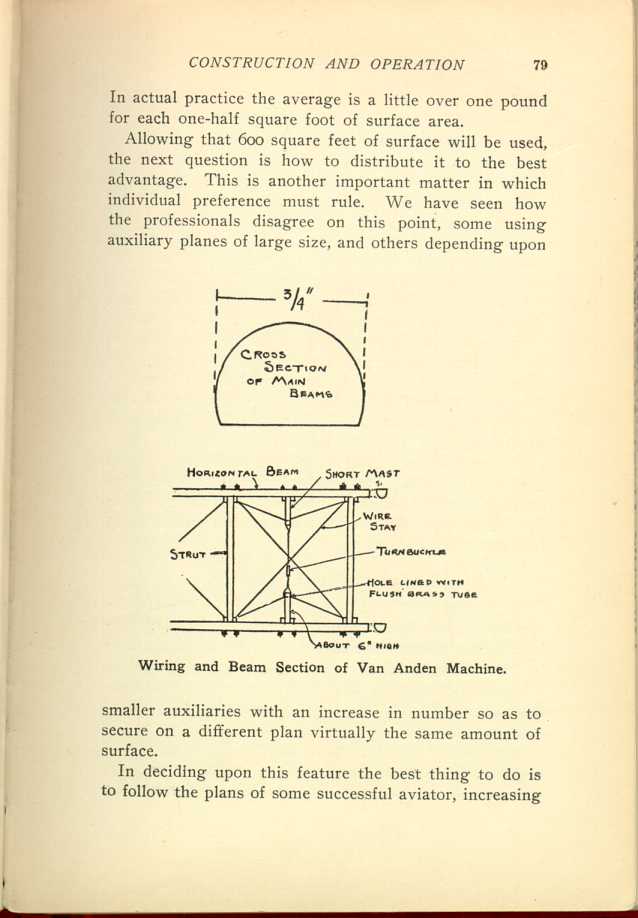
Wiring and Beam Section of Van Anden Machine.
[Description: Black and white illustration: Two-part diagram of beam width
and wiring.]
In deciding upon this feature the best thing to do is to follow the plans of some successful aviator, increasing
The Cost of Production.
Cost of production will be of interest to the amateur who essays to construct a flying machine. Assuming that the size decided upon is double that of the glider the material for the framework, timber, cloth, wire, etc., will cost a little more than double. This is because it must be heavier in proportion to the increased size of the framework, and heavy material brings a larger price than the lighter goods. If we allow $20 as the cost of the glider material it will be safe to put down the cost of that required for a real flying machine framework at $60, provided the owner builds it himself.
As regards the cost of motor and similar equipment it can only be said that this depends upon the selection made. There are some reliable aviation motors which may be had as low as $500, and there are others which cost as much as $2,000.
Services of Expert Necessary.
No matter what kind of a motor may be selected the services of an expert will be necessary in its proper installation unless the amateur has considerable genius in this line himself. As a general thing $25 should be a liberal allowance for this work. No matter how carefully the engine may be placed and connected it will be largely a matter of luck if it is installed in exactly the proper manner at the first attempt. The chances are that several alterations, prompted by the results of trials, will have to be made. If this is the case the expert's
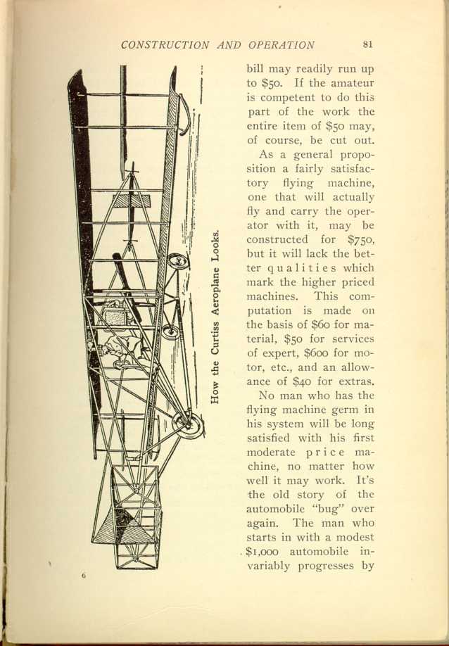
How the Curtis Aeroplane Looks.
[Description: Black and white illustration: Man operating aeroplane.]As a general proposition a fairly satisfactory flying machine, one that will actually fly and carry the operator with it, may be constructed for $750, but it will lack the better qualities which mark the higher priced machines. This computation is made on the basis of $60 for material, $50 for services of expert, $600 for motor, etc., and an allowance of $40 for extras.
No man who has the flying machine germ in his system will be long satisfied with his first moderate price machine, no matter how well it may work. It's the old story of the automobile "bug" over again. The man who starts in with a modest $1,000 automobile invariably progresses by
It's exactly the same way with the flying machine convert. The more proficient he becomes in the manipulation of his car, the stronger becomes the desire to fly further and stay in the air longer than the rest of his brethren. This necessitates larger, more powerful, and more expensive machines as the work of the germ progresses.
Speed Affects Weight Capacity.
Don't overlook the fact that the greater speed you can attain the smaller will be the surface area you can get along with. If a machine with 500 square feet of sustaining surface, traveling at a speed of 40 miles an hour, will carry a weight of 1,200 pounds, we can cut the sustaining surface in half and get along with 250 square feet, provided a speed of 60 miles an hour can be obtained. At 100 miles an hour only 80 square feet of surface area would be required. In both instances the weight sustaining capacity will remain the same as with the 500 square feet of surface area—1,200 pounds.
One of these days some mathematical genius will figure out this problem with exactitude and we will have a dependable table giving the maximum carrying capacity of various surface areas at various stated speeds, based on the dimensions of the advancing edges. At present it is largely a matter of guesswork so far as making accurate computation goes. Much depends upon the shape of the machine, and the amount of surface offering resistance to the wind, etc.
| CHAPTER VIII.
THE REAL FLYING MACHINE. Flying Machines: Construction and Operation: A Practical Book Which Shows, in Illustrations, Working Plans and Text, How to Build and Navigate the Modern Airship. | ||