| CHAPTER XXVI.
MONOPLANES, TRIPLANES, MULTIPLANES. Flying Machines: Construction and Operation: A Practical Book Which Shows, in Illustrations, Working Plans and Text, How to Build and Navigate the Modern Airship. | ||
26. CHAPTER XXVI.
MONOPLANES, TRIPLANES, MULTIPLANES.
Until recently, American aviators had not given serious attention to any form of flying machines aside from biplanes. Of the twenty-one monoplanes competing at the International meet at Belmont Park, N. Y., in November, 1910, only three makes were handled by Americans. Moissant and Drexel navigated Bleriot machines, Harkness an Antoinette, and Glenn Curtiss a single decker of his own construction. On the other hand the various foreign aviators who took part in the meet unhesitatingly gave preference to monoplanes.
Whatever may have been the cause of this seeming prejudice against the monoplane on the part of American air sailors, it is slowly being overcome. When a man like Curtiss, who has attained great success with biplanes, gives serious attention to the monoplane form of construction and goes so far as to build and successfully operate a single surface machine, it may be taken for granted that the monoplane is a fixture in this country.
Dimensions of Monoplanes.
The makes, dimensions and equipment of the various monoplanes used at Belmont Park are as follows:
Bleriot—(Moissant, operator)—plane length 23 feet, extreme breadth 28 feet, surface area 160 square feet, 7-cylinder, 50 h. p. Gnome engine, Chauviere propeller, 7 feet 6 inches diameter, 1,200 r. p. m.
Bleriot—(Drexel, operator)—exactly the same as Moissant's machine.
Antoinette—(Harkness, operator)—plane length 42 feet,
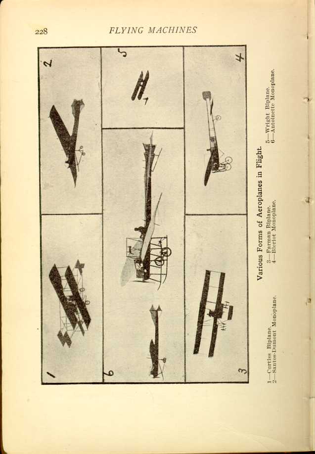
Various Forms of Aeroplanes in Flight.
1—Curtis Biplane. 2—Santos-Dumont Monoplane. 3—Farman Biplane.
4—Bleriot Monoplane. 5—Wright Biplane. 6—Antoinette Monoplane.
[Description: Six black and white photographs of various aeroplanes in
flight.]
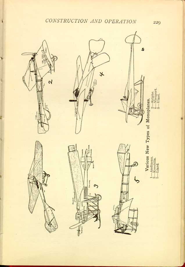
Various New Types of Monoplanes.
1—Andineau. 2—Sylphe. 3—Koechlin. 4—Nieuport. 5—Liard. 6—Vinet.
[Description: Six black and white illustrations of various monoplanes.]
Curtiss—(Glenn H. Curtiss, operator)—plane length 25 feet, extreme breadth 26 feet, surface area 130 square feet, Curtiss 8-cylinder, 60 h. p. motor, Paragon propeller, 7 feet in diameter, 1,200 r. p. m.
With one exception Curtiss had the smallest machine of any of those entering into competition. The smallest was La Demoiselle, made by Santos-Dumont, the proportions of which were: plane length 20 feet, extreme breadth 18 feet, surface area 100 square feet, Clement-Bayard 2-cylinder, 30 h. p. motor, Chauviere propeller, 6 feet 6 inches in diameter, 1,100 r. p. m.
Winnings Made with Monoplanes.
Operators of monoplanes won a fair share of the cash prizes. They won $30,283 out of a total of $63,250, to say nothing about Grahame-White's winnings. The latter won $13,600, but part of his winning flights were made in a Bleriot monoplane, and part in a Farman machine. Aside from Grahame-White the winnings were divided as follows: Moissant (Bleriot) $13,350; Latham (Antoinette) $8,183; Aubrun (Bleriot) $2,400; De Lesseps (Bleriot) $2,300; Drexel (Bleriot) $1,700; Radley (Bleriot) $1,300; Simon (Bleriot) $750; Andemars (Clement-Bayard) $100; Barrier (Bleriot) $100.
Out of a total of $30,283, operators of Bleriot machines won $21,900, again omitting Grahame-White's share. If the winnings with monoplane and biplane could be divided so as to show the amount won with each type of machine the credit side of the Bleriot account would be materially enlarged.
The Most Popular Monoplanes.
While the number of successful monoplanes is increasing rapidly, and there is some feature of advantage in nearly all the new makes, interest centers chiefly in the Santos-Dumont, Antoinette and Bleriot machines. This is because more has
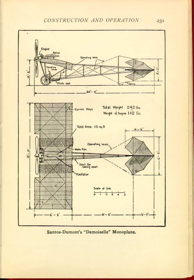
Santos-Dumont's "Demoiselle" Monoplane.
[Description: Black and white illustration: Two-part diagram of monoplane, from side and from above.]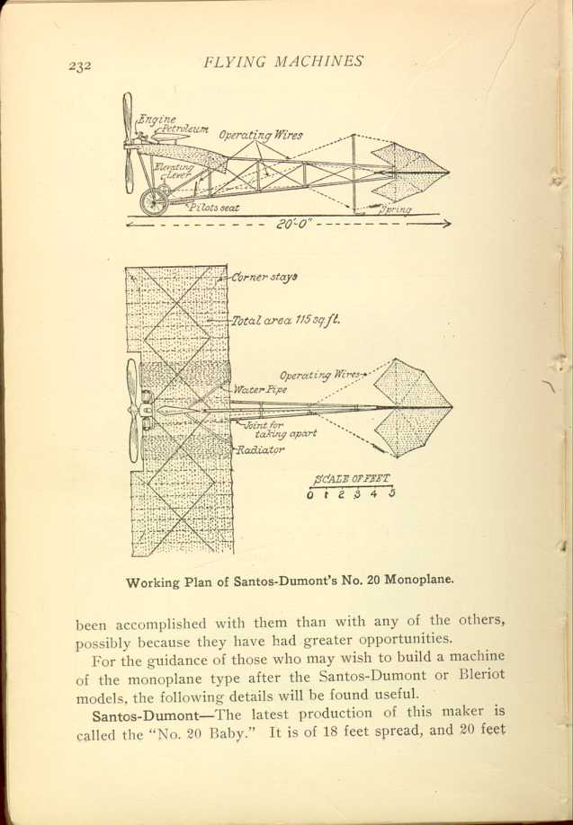
Working Plan of Santos-Dumont's No. 20 Monoplane.
[Description: Black and white illustration: Two-part diagram of monoplane, from side and from above.]For the guidance of those who may wish to build a machine of the monoplane type after the Santos-Dumont or Bleriot models, the following details will be found useful.
Santos-Dumont—The latest production of this maker is called the "No. 20 Baby." It is of 18 feet spread, and 20 feet
Bamboo is used in the construction of the body frame, and also for the frame of the tail. The body frame consists of three bamboo poles about 2 inches in diameter at the forward end and tapering to about 1 inch at the rear. These poles are jointed with brass sockets near the rear of the main plane so they may be taken apart easily for convenience in housing or transportation. The main plane is built upon four transverse spars of ash, set at a slight dihedral angle, two being placed on each side of the central bamboo. These spars are about 2 inches wide by 1 1/8-inch deep for a few feet each side of the center of the machine, and from there taper down to an inch in depth at the center bamboo, and at their outer ends, but the width remains the same throughout their entire length. The planes are double surfaced with silk and laced above and below the bamboo ribs which run fore and aft under the main spars and terminate in a forked clip through which a wire is strung for lacing on the silk. The tail consists of a horizontal and vertical surface placed on a universal joint about 10 feet back of the rear edge of the main plane. Both of these surfaces are flat and consist of a silk covering stretched upon bamboo ribs. The horizontal surface is 6 feet 5 inches across, and 4 feet 9 inches from front to back. The vertical surface is of the same width (6 feet 5 inches) but is only 3 feet 7 inches from front to back. All the details of construction are shown in the accompanying illustration.
Power is furnished by a very light (110 pounds) Darracq motor, of the double-opposed-cylinder type. It has a bore of
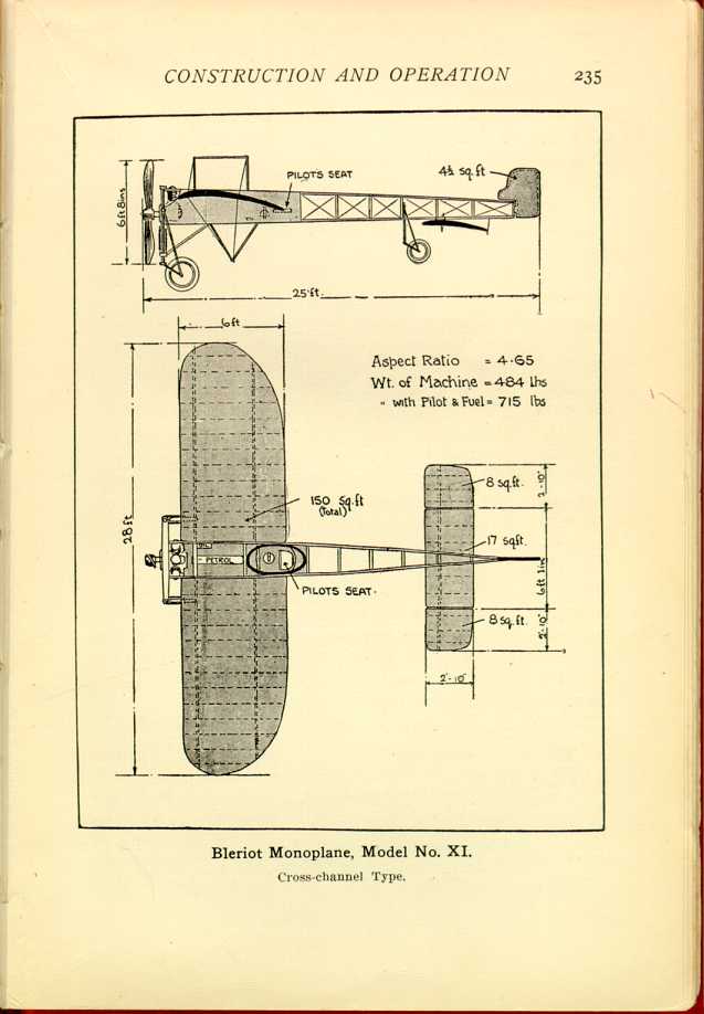
Bleriot—No. XI, the latest of the Bleriot productions, and the greatest record maker of the lot, is 28 feet in spread of main plane, and depth of 6 feet in largest part. This would give a main surface of 168 square feet, but as the ends of the plane are sharply tapered from the rear, the actual surface is reduced to 150 square feet. Projecting from the main frame is an elongated tail (shown in the illustration) which carries the horizontal and vertical rudders. The former is made in three sections. The center piece is 6 feet 1 inch in spread, and 2 feet 10 inches in depth, containing 17 square feet of surface. The end sections, which are made movable for warping purposes, are each 2 feet 10 inches square, the combined surface area in the entire horizontal rudder being 33 square feet. The vertical rudder contains 4 1/2 square feet of surface, making the entire supporting area 187 1/2 square feet.
From the outer end of the propeller shaft in front to the extreme rear edge of the vertical rudder, the machine is 25 feet deep. Deducting the 6-foot depth of the main plane leaves 19 feet as the length of the rudder beam and rudders. The motor equipment consists of a 3-cylinder, air-cooled engine of about 30 h. p. placed at the front end of the body frame, and carrying on its crankshaft a two-bladed propeller 6 feet 8 inches in diameter. The engine speed is about 1,250 r. p. m. at which the propeller develops a thrust of over 200 pounds.
The Bleriot XI complete weighs 484 pounds, and with operator and fuel supply ready for a 25-or 30-mile flight, 715 pounds. One peculiarity of the Bleriot construction is that, while the ribs of the main plane are curved, there is no preliminary bending of the pieces as in other forms of construction. Bleriot has his rib pieces cut a little longer than required and, by springing them into place, secures the necessary curvature. A good view of the Bleriot plane framework is given on page 63.
Combined Triplane and Biplane.
At Norwich, Conn., the Stebbins-Geynet Co., after several years of experiment, has begun the manufacture of a combination triplane and biplane machine. The center plane, which is located about midway between the upper and lower surfaces, is made removable. The change from triplane to biplane, or vice versa, may be readily made in a few minutes. The constructors claim for this type of air craft a large supporting surface area with the minimum of dimensions in planes. Although this machine has only 24-foot spread and is only 26 feet over all, its total amount of supporting area is 400 square feet; weight, 600 pounds in flying order, and lifting capacity approximately 700 pounds more.
The frame is made entirely of a selected grade of Oregon spruce, finished down to a smooth surface and varnished. All struts are fish-shaped and set in aluminum sockets, which are bolted to top and lower beams with special strong bolts of small diameter. The middle plane is set inside the six uprights and held in place by aluminum castings. A flexible twisted seven-strand wire cable and Stebbins-Geynet turnbuckles are used for trussing.
The top plane is in three sections, laced together. It has a 24-foot spread and is 7 feet in depth. The middle plane is in two sections each of 7 1/2 feet spread and 6 feet in depth. The center ends of the middle plane sections do not come within 5 feet of joining, this open space being left for the engine. The bottom plane is of 16 feet spread and 5 feet in depth. It will thus be seen that the planes overhang one another in depth, the bottom one being the smallest in this respect. The planes are set at an angle of 9 degrees, and there is a clear space of 3 1/2 feet between each, making the total distance from the bottom to the top plane a trifle over 7 feet. The total supporting surface in the main planes is 350 square feet. By arranging the three plane surfaces at an angle as described and varying their
The ribs are made of laminated spruce, finished down to 1/2 x 3/4-inch cross section dimensions, with a curvature of about 1 in 20, and fastened to the beams with special aluminum castings. Number 2 Naiad aeroplane cloth is used in covering the planes, with pockets sewn in for the ribs.
Two combination elevating rudders are set up well in front, each having 18 square feet of supporting area. These rudders are arranged to work in unison, independently, or in opposite directions. In the Model B machine, there are also two small rear elevating rudders, which work in unison with the front rudders. One vertical rudder of 10 square feet is suspended in the rear of a small stationary horizontal plane in Model A, while the vertical rudder on Model B is only 6 square feet in size. The elevating rudders are arranged so as to act as stabilizing planes when the machine is in flight. The wing tips are held in place with a special two-piece casting which forms a hinge, and makes a quick detachable joint. Wing tips are also used in balancing.
Model A is equipped with a Cameron 25-30 h. p., 4-cylinder, air-cooled motor. On Model B a Holmes rotary 7-cylinder motor of 4x4-inch bore and stroke is used.
Positive control is secured by use of the Stebbins-Geynet "auto-control" system. A pull or push movement operates the elevating rudders, while the balancing is done by means of side movements or slight turns. The rear vertical rudder is manipulated by means of a foot lever.
New Cody Biplane.
Among the comparatively new biplanes is one constructed by Willard F. Cody, of London, Eng., the principal distinctive feature of which is an automatic control which works independently of the hand levers. For the other control a long lever carrying a steering wheel furnishes all the necessary control
The spread of the planes is 46 feet 6 inches and the width 6 feet 6 inches. The ailerons jut out 1 foot 6 inches on each side of the machine and are 13 feet 6 inches long. The cross-shaped tail is supported by an outrigger composed of two long bamboos and of this the vertical plane is 9 feet by 4 feet, while the horizontal plane is 8 feet by 4 feet. The over-all length of the machine is 36 feet. The lifting surface is 857 square feet. It will weigh, with a pilot, 1,450 pounds. The distance between the main planes is 8 feet 6 inches, which is a rather notable feature in this flyer.
The propeller has a diameter of 11 feet and 2 inches with a 13-foot 6-inch pitch; it is driven at 560 revolutions by a chain, and the gear reduction between the chain and propeller shaft is two to one.
The machine from elevator to tail plane bristles in original points. The hump in the ribs has been cut away entirely, so that although the plane is double surfaced, the surfaces are closest together at a point which approximates the center of pressure. The plane is practically of two stream-line forms, of which one is the continuation of the other. This construction, claims the inventor, will give increased lift, and decreased head resistance. The trials substantiate this, as the angle of incidence in flying is only about one in twenty-six.
The ribs in the main planes are made of strips of silver spruce one-half by one-half inch, while those in the ailerons are solid and one-fourth inch thick. In the main planes the fabric is held down with thin wooden fillets. Cody's planes are noted for their neatness, rigidity and smoothness. Pegamoid fabric is used throughout.
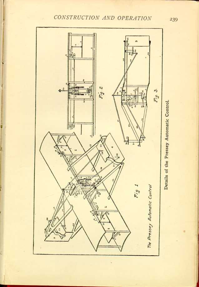
Pressey Automatic Control.
Another ingenious system of automatic control has been perfected by Dr. J. B. Pressey, of Newport News, Va. The aeroplane is equipped with a manually operated, vertical rudder, (3), at the stern, and a horizontal, manually operated, front control, (4), in front. At the ends of the main plane, and about midway between the upper and lower sections thereof, there are supplemental planes, (5).
In connection with these supplemental planes (5), there is employed a gravity influenced weight, the aviator in his seat, for holding them in a horizontal, or substantially horizontal, position when the main plane is traveling on an even keel; and for causing them to tip when the main plane dips laterally, to port or starboard, the planes (5) having a lifting effect upon the depressed end of the main plane, and a depressing effect upon the lifted end of the main plane, so as to correct such lateral dip of the main plane, and restore it to an even keel. To the forward, upper edge of planes (5) connection is made by means of rod (13) to one arm of a bellcrank lever, (14) the latter being pivotally mounted upon a fore and aft pin (15), supported from the main plane; and the other arms of the port and starboard bellcrank levers (16), are connected by rod (17), which has an eye (18), for receiving the segmental rod (19), secured to and projecting from cross bar on seat supporting yoke (7). When, therefore, the main plane tips downwardly on the starboard side, the rod (17) will be moved bodily to starboard, and the starboard balancing plane (5) will be inclined so as to raise its forward edge and depress its rear edge, while, at the same time, the port balancing plane (5), will be inclined so as to depress its forward edge, and raise its rear edge, thereby causing the starboard balancing plane to exert a lifting effect, and the port balancing plane to exert a depressing effect upon the main plane, with the result of restoring the main plane to an even keel, at which time the balancing planes (5), will have resumed their normal, horizontal position.
When the main plane dips downwardly on the port side, a reverse action takes place, with the like result of restoring the main plane to an even keel. In order to correct forward and aft dip of the main plane, fore and aft balancing planes (20) and (23) are provided. These planes are carried by transverse rock shafts, which may be pivotally mounted in any suitable way, upon structures carried by main plane. In the present instance, the forward balancing plane is pivotally mounted in extensions (21) of the frame (22) which carries the forward, manually operated, horizontal ascending and descending plane
It is absolutely necessary, in making a turn with an aeroplane, if that turn is to be made in safety, that the main plane shall be inclined, or "banked," to a degree proportional to the radius of the curve and to the speed of the aeroplane. Each different curve, at the same speed, demands a different inclination, as is also demanded by each variation in speed in rounding like curves. This invention gives the desired result with absolute certainty.
The Sellers' Multiplane.
Another innovation is a multiplane, or four-surfaced machine, built and operated by M. B. Sellers, formerly of Grahn, Ky., but now located at Norwood, Ga. Aside from the use of four sustaining surfaces, the novelty in the Sellers machine lies in the fact that it is operated successfully with an 8 h. p. motor, which is the smallest yet used in actual flight. In describing his work, Mr. Sellers says his purpose has been to develop the efficiency of the surfaces to a point where flight may be obtained with the minimum of power and, judging by the results accomplished, he has succeeded. In a letter written to the authors of this book, Mr. Sellers says:
"I dislike having my machine called a quadruplane, because the number of planes is immaterial; the distinctive feature being the arrangement of the planes in steps; a better name would be step aeroplane, or step plane.
"The machine as patented, comprises two or more planes arranged in step form, the highest being in front. The machine I am now using has four planes 3 ft. x 18 ft.; total about 200 square feet; camber (arch) 1 in 16.
"The vertical keel is for lateral stability; the rudder for
direction. This is the first machine (so far as I know) to have a
combination of wheels and runners or skids (Oct. 1908). The
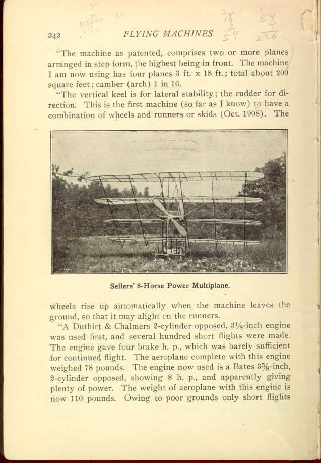
Sellers' 8-Horse Power Multiplane.
[Description: Black and white photograph: multiplane, from front.]
"A Duthirt & Chalmers 2-cylinder opposed, 3 1/8-inch engine was used first, and several hundred short flights were made. The engine gave four brake h. p., which was barely sufficient for continued flight. The aeroplane complete with this engine weighed 78 pounds. The engine now used is a Bates 3 5/8-inch, 2-cylinder opposed, showing 8 h. p., and apparently giving plenty of power. The weight of aeroplane with this engine is now 110 pounds. Owing to poor grounds only short flights
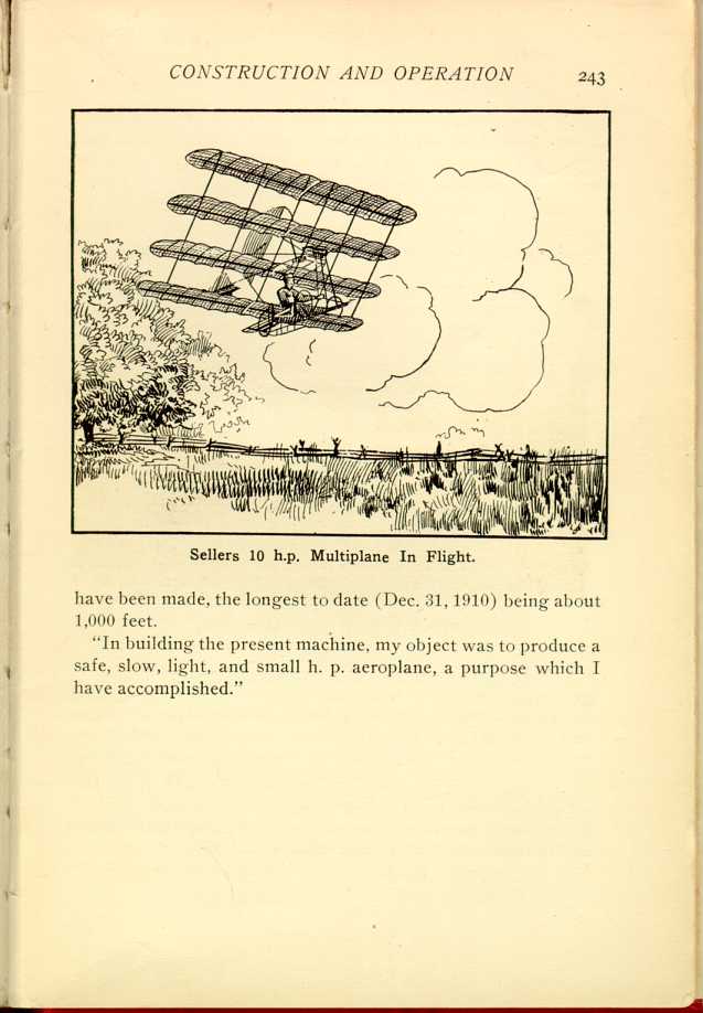
Sellers 10 h.p. Multiplane In Flight.
[Description: Black and white illustration: Multiplane in flight.]"In building the present machine, my object was to produce a safe, slow, light, and small h. p. aeroplane, a purpose which I have accomplished."
| CHAPTER XXVI.
MONOPLANES, TRIPLANES, MULTIPLANES. Flying Machines: Construction and Operation: A Practical Book Which Shows, in Illustrations, Working Plans and Text, How to Build and Navigate the Modern Airship. | ||