| CHAPTER VII.
PUTTING ON THE RUDDER. Flying Machines: Construction and Operation: A Practical Book Which Shows, in Illustrations, Working Plans and Text, How to Build and Navigate the Modern Airship. | ||
7. CHAPTER VII.
PUTTING ON THE RUDDER.
Gliders as a rule have only one rudder, and this is in the rear. It tends to keep the apparatus with its head to the wind. Unlike the rudder on a boat it is fixed and immovable. The real motor-propelled flying machine, generally has both front and rear rudders manipulated by wire cables at the will of the operator.
Allowing that the amateur has become reasonably expert in the manipulation of the glider he should, before constructing an actual flying machine, equip his glider with a rudder.
Cross Pieces for Rudder Beam.
To do this he should begin by putting in a cross piece, 2 feet long by 1/4 x 3/4 inches between the center struts, in the lower plane. This may be fastened to the struts with bolts or braces. The former method is preferable. On this cross piece, and on the rear frame of the plane itself, the rudder beam is clamped and bolted. This rudder beam is 8 feet 11 inches long. Having put these in place duplicate them in exactly the same manner and dimensions from the upper frame The cross pieces on which the ends of the rudder beams are clamped should be placed about one foot in advance of the rear frame beam.
The Rudder Itself.
The next step is to construct the rudder itself. This
The rudder beams form the top and bottom frames of the vertical rudder. To these are bolted and clamped two upright pieces, 3 feet, 10 inches in length, and 3/4 inch in cross section. These latter pieces are placed about two feet apart. This completes the framework of the vertical rudder. See next page (59).
For the horizontal rudder you will require two strips 6 feet long, and four 2 feet long. Find the exact center of the upright pieces on the vertical rudder, and at this spot fasten with bolts the long pieces of the horizontal, placing them on the outside of the vertical strips. Next join the ends of the horizontal strips with the 2-foot pieces, using small screws and corner braces. This done you will have two of the 2-foot pieces left. These go in the center of the horizontal frame, "straddling" the vertical strips, as shown in the illustration.
The framework is to be covered with cloth in the same manner as the planes. For this about ten yards will be needed.
Strengthening the Rudder.
To ensure rigidity the rudder must be stayed with guy wires. For this purpose the No. 12 piano wire is the best. Begin by running two of these wires from the top eye-bolts of stanchions 3 and 4, page 37, to rudder beam where it joins the rudder planes, fastening them at the bottom. Then run two wires from the top of the rudder beam at the same point, to the bottom eye-bolts of the same stanchions. This will give you four diagonal wires reaching from the rudder beam to the top and bottom planes of the glider. Now, from the outer
The framework of the rudder planes is then to be braced in the same way, which will take eight more wires, four for each rudder plane. All the wires are to be connected at one end with turn-buckles so the tension may be regulated as desired.
In forming the rudder frame it will be well to mortise the corners, tack them together with small nails, and then put in a corner brace in the inside of each joint. In doing this bear in mind that the material to be thus fastened is light, and consequently the lightest of nails, screws, bolts and corner pieces, etc., is necessary.
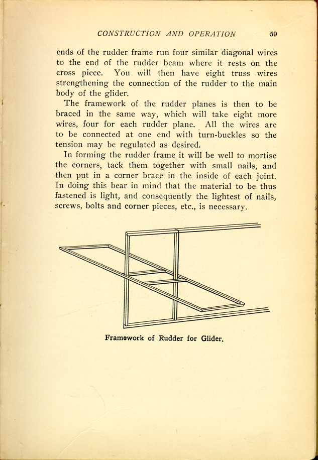
Framework of Rudder for Glider.
[Description: Black and white illustration: Framework of rudder.]
| CHAPTER VII.
PUTTING ON THE RUDDER. Flying Machines: Construction and Operation: A Practical Book Which Shows, in Illustrations, Working Plans and Text, How to Build and Navigate the Modern Airship. | ||