| EVOLUTION OF TWO-SURFACE FLYING MACHINE.
By Octave Chanute. Flying Machines: Construction and Operation: A Practical Book Which Shows, in Illustrations, Working Plans and Text, How to Build and Navigate the Modern Airship. | ||
1. EVOLUTION OF TWO-SURFACE FLYING MACHINE.
By Octave Chanute.
I am asked to set forth the development of the "two-surface" type of flying machine which is now used with modifications by Wright Brothers, Farman, [1]Delagrange, Herring and others.
This type originated with Mr. F. H. Wenham, who
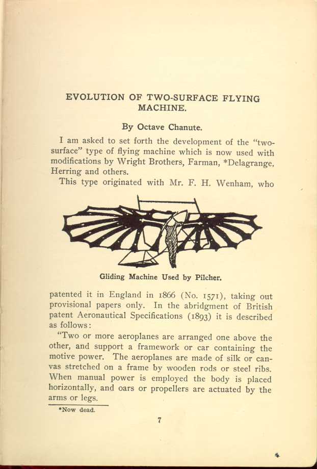
Gliding Machine Used by Pilcher.
[Description: Black and white illustration: Man operating bat-winged glider.]
"Two or more aeroplanes are arranged one above the other, and support a framework or car containing the motive power. The aeroplanes are made of silk or canvas stretched on a frame by wooden rods or steel ribs. When manual power is employed the body is placed horizontally, and oars or propellers are actuated by the arms or legs.
"A start may be obtained by lowering the legs and running down hill or the machine may be started from a moving carriage. One or more screw propellers may be applied for propelling when steam power is employed.
On June 27, 1866, Mr. Wenham read before the "Aeronautical Society of Great Britain," then recently organized, the ablest paper ever presented to that society, and thereby breathed into it a spirit which has continued to this day. In this paper he described his observations of birds, discussed the laws governing flight as to the surfaces and power required both with wings and screws, and he then gave an account of his own experiments with models and with aeroplanes of sufficient size to carry the weight of a man.
Second Wenham Aeroplane.
His second aeroplane was sixteen feet from tip to tip. A trussed spar at the bottom carried six superposed bands of thin holland fabric fifteen inches wide, connected with vertical webs of holland two feet apart, thus virtually giving a length of wing of ninety-six feet and one hundred and twenty square feet of supporting surface. The man was placed horizontally on a base board beneath the spar. This apparatus when tried in the wind was found to be unmanageable by reason of the fluttering motions of the fabric, which was insufficiently stiffened with crinoline steel, but Mr. Wenham pointed out that this in no way invalidated the principle of the apparatus, which was to obtain large supporting surfaces without increasing unduly the leverage and consequent weight of spar required, by simply superposing the surfaces.
This principle is entirely sound and it is surprising that it is, to this day, not realized by those aviators who are hankering for monoplanes.
Experiments by Stringfellow.
The next man to test an apparatus with superposed surfaces was Mr.
Stringfellow, who, becoming much impressed with Mr. Wenham's proposal,
produced a largish model at the exhibition of the Aeronautical Society
in 1868. It consisted of three superposed surfaces aggregating
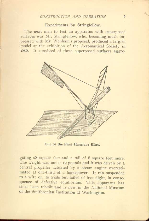
One of the First Hargrave Kites.
[Description: Black and white illustration: Kite apparatus.]
Linfield's Unsuccessful Efforts.
In 1878 Mr. Linfield tested an apparatus in England consisting of a cigar-shaped car, to which was attached on each side frames five feet square, containing each twenty-five superposed planes of stretched and varnished linen eighteen inches wide, and only two inches apart, thus reminding one of a Spanish donkey with panniers. The whole weighed two hundred and forty pounds. This was tested by being mounted on a flat car behind a locomotive going 40 miles an hour. When towed by a line fifteen feet long the apparatus rose only a little from the car and exhibited such unstable equilibrium that the experiment was not renewed. The lift was only about one-third of what it would have been had the planes been properly spaced, say their full width apart, instead of one-ninth as erroneously devised.
Renard's "Dirigible Parachute."
In 1889 Commandant Renard, the eminent superintendent of the French Aeronautical Department, exhibited at the Paris Exposition of that year, an apparatus experimented with some years before, which he termed a "dirigible parachute." It consisted of an oviform body to which were pivoted two upright slats carrying above the body nine long superposed flat blades spaced about one-third of their width apart. When this apparatus was properly set at an angle to the longitudinal axis of the body and dropped from a balloon, it travelled back against the wind for a considerable distance before alighting. The course could be varied by a rudder. No practical application seems to have been made of this device by the French War Department, but Mr. J. P. Holland, the inventor of the submarine boat which bears his name, proposed in 1893 an arrangement of pivoted
Phillips Fails on Stability Problem.
In 1893 Mr. Horatio Phillips, of England, after some very interesting
experiments with various wing sections, from which he deduced
conclusions as to the shape of
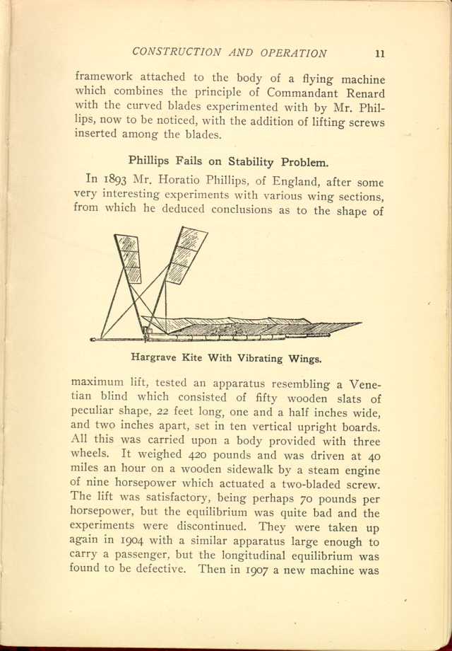
Hargrave Kite With Vibrating Wings.
[Description: Black and white illustration: Kite apparatus with two
extending panels.]
Hargrave's Kite Experiments.
After experimenting with very many models and building no less than eighteen monoplane flying model machines, actuated by rubber, by compressed air and by steam, Mr. Lawrence Hargrave, of Sydney, New South Wales, invented the cellular kite which bears his name and made it known in a paper contributed to the Chicago Conference on Aerial Navigation in 1893, describing several varieties. The modern construction is well known, and consists of two cells, each of superposed surfaces with vertical side fins, placed one behind the other and connected by a rod or frame. This flies with great steadiness without a tail. Mr. Hargrave's idea was to use a team of these kites, below which he proposed to suspend a motor and propeller from which a line would be carried to an anchor in the ground. Then by actuating the propeller the whole apparatus would move forward, pick up the anchor and fly away. He said: "The next step is clear enough, namely, that a flying machine with acres of surface can be safely got under way or anchored and hauled to the ground by means of the string of kites."
The first tentative experiments did not result well and emphasized the necessity for a light motor, so that Mr. Hargrave has since been engaged in developing one, not
Experiments With Glider Model.
And here a curious reminiscence may be indulged in. In 1888 the
present writer experimented with a two-cell
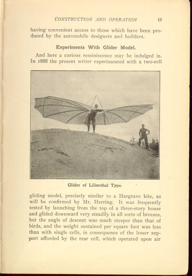
Glider of Lilienthal Type.
[Description: Black and white photograph: Man operating bat-winged glider.]
Sir Hiram Maxim also introduced fore and aft superposed surfaces in his wondrous flying machine of 1893, but he relied chiefly for the lift upon his main large surface and this necessitated so many guys, to prevent distortion, as greatly to increase the head resistance and this, together with the unstable equilibrium, made it evident that the design of the machine would have to be changed.
How Lilienthal Was Killed.
In 1895, Otto Lilienthal, the father of modern aviation, the man to whose method of experimenting almost all present successes are due, after making something like two thousand glides with monoplanes, added a superposed surface to his apparatus and found the control of it much improved. The two surfaces were kept apart by two struts or vertical posts with a few guy wires, but the connecting joints were weak and there was nothing like trussing. This eventually cost his most useful life. Two weeks before that distressing loss to science, Herr Wilhelm Kress, the distinguished and veteran aviator of Vienna, witnessed a number of glides by Lilienthal with his double-decked apparatus. He noticed that it was much wracked and wobbly and wrote to me after the accident: "The connection of the wings and the steering arrangement were very bad and unreliable. I warned Herr Lilienthal very seriously. He promised me that he would soon put it in order, but I fear that he did not attend to it immediately."
In point of fact, Lilienthal had built a new machine, upon a different principle, from which he expected great results, and intended to make but very few more flights
Experiments by the Writer.
In 1896, assisted by Mr. Herring and Mr. Avery, I experimented with
several full sized gliding machines,
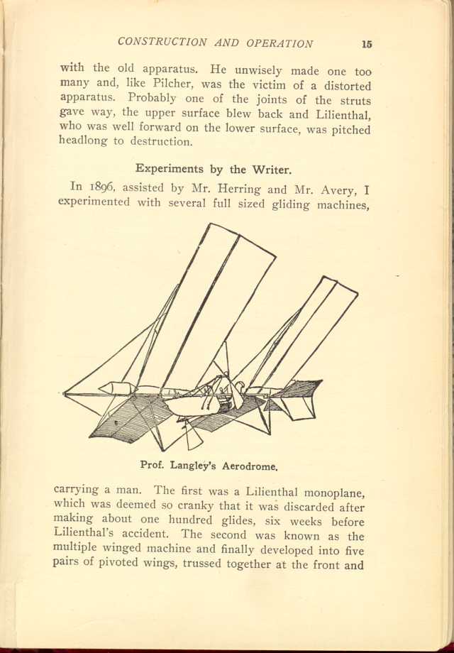
Prof. Langley's Aerodome.
[Description: Black and white illustration: what looks like a boat with four
large wing panels.]
Being a builder of bridges, I trussed these surfaces together, in order to obtain strength and stiffness. When tested in gliding flight the lower surface was found too near the ground. It was taken off and the remaining apparatus now consisted of two surfaces connected together by a girder composed of vertical posts and diagonal ties, specifically known as a "Pratt truss." Then Mr. Herring and Mr. Avery together devised and put on an elastic attachment to the tail. This machine proved a success, it being safe and manageable. Over 700 glides were made with it at angles of descent of 8 to 10 degrees, or one in six to one in seven.
First Proposed by Wenham.
The elastic tail attachment and the trussing of the connecting frame of the superposed wings were the only novelties in this machine, for the superposing of the surfaces had first been proposed by Wenham, but in accordance with the popular perception, which bestows all the credit upon the man who adds the last touch making for success to the labors of his predecessors, the machine has since been known by many persons as the "Chanute type" of gliders, much to my personal gratification.
It has since been improved in many ways. Wright Brothers, disregarding the fashion which prevails among birds, have placed the tail in front of their apparatus and called it a front rudder, besides placing the operator in
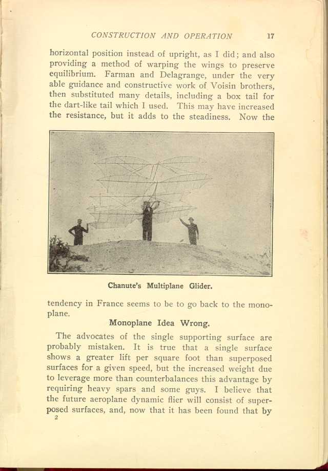
Chanute's Multiplane Glider.
[Description: Black and white photograph: Man holding a glider with four rows of two wings; two other men assist.]Monoplane Idea Wrong.
The advocates of the single supporting surface are probably mistaken. It is true that a single surface shows a greater lift per square foot than superposed surfaces for a given speed, but the increased weight due to leverage more than counterbalances this advantage by requiring heavy spars and some guys. I believe that the future aeroplane dynamic flier will consist of superposed surfaces, and, now that it has been found that by
| EVOLUTION OF TWO-SURFACE FLYING MACHINE.
By Octave Chanute. Flying Machines: Construction and Operation: A Practical Book Which Shows, in Illustrations, Working Plans and Text, How to Build and Navigate the Modern Airship. | ||