| CHAPTER V.
CONSTRUCTING A GLIDING MACHINE. Flying Machines: Construction and Operation: A Practical Book Which Shows, in Illustrations, Working Plans and Text, How to Build and Navigate the Modern Airship. | ||
5. CHAPTER V.
CONSTRUCTING A GLIDING MACHINE.
First decide upon the kind of a machine you want—monoplane, biplane, or triplane. For a novice the biplane will, as a rule, be found the most satisfactory as it is more compact and therefore the more easily handled. This will be easily understood when we realize that the surface of a flying machine should be laid out in proportion to the amount of weight it will have to sustain. The generally accepted rule is that 152 square feet of surface will sustain the weight of an average-sized man, say 170 pounds. Now it follows that if these 152 square feet of surface are used in one plane, as in the monoplane, the length and width of this plane must be greater than if the same amount of surface is secured by using two planes—the biplane. This results in the biplane being more compact and therefore more readily manipulated than the monoplane, which is an important item for a novice.
Glider the Basis of Success.
Flying machines without motors are called gliders. In making a flying machine you first construct the glider. If you use it in this form it remains a glider. If you install a motor it becomes a flying machine. You must have a good glider as the basis of a successful flying machine.
It will be well for the novice, the man who has never had any experience as an aviator, to begin with a glider
Plans for Handy Glider.
A glider with a spread (advancing edge) of 20 feet, and a breadth or depth of 4 feet, will be about right to begin with. Two planes of this size will give the 152 square yards of surface necessary to sustain a man's weight. Remember that in referring to flying machine measurements "spread" takes the place of what would ordinarily be called "length," and invariably applies to the long or advancing edge of the machine which cuts into the air. Thus, a glider is spoken of as being 20 feet spread, and 4 feet in depth. So far as mastering the control of the machine is concerned, learning to balance one's self in the air, guiding the machine in any desired direction by changing the position of the body, etc., all this may be learned just as readily, and perhaps more so, with a 20-foot glider than with a larger apparatus.
Kind of Material Required.
There are three all-important features in flying machine construction, viz.: lightness, strength and extreme rigidity. Spruce is the wood generally used for glider frames. Oak, ash and hickory are all stronger, but they are also considerably heavier, and where the saving of weight is essential, the difference is largely in favor of spruce. This will be seen in the following table:
| Wood | Weight per cubic ft. in lbs. | Tensile Strength lbs. per sq. in. | Compressive Strength lbs. per sq. in. |
| Hickory | 53 | 12,000 | 8,500 |
| Oak | 50 | 12,000 | 9,000 |
| Ash | 38 | 12,000 | 6,000 |
| Walnut | 38 | 8,000 | 6,000 |
| Spruce | 25 | 8,000 | 5,000 |
| Pine | 25 | 5,000 | 4,500 |
Considering the marked saving in weight spruce has a greater percentage of tensile strength than any of the other woods. It is also easier to find in long, straight-grained pieces free from knots, and it is this kind only that should be used in flying machine construction.
You will next need some spools or hanks of No. 6 linen shoe thread, metal sockets, a supply of strong piano wire, a quantity of closely-woven silk or cotton cloth, glue, turnbuckles, varnish, etc.
Names of the Various Parts.
The long strips, four in number, which form the front and rear edges of the upper and lower frames, are called the horizontal beams. These are each 20 feet in length. These horizontal beams are connected by upright strips,
Quantity and Cost of Material.
For the horizontal beams four pieces of spruce, 20 feet long, 1 1/2 inches wide and 3/4 inch thick are necessary. These pieces must be straight-grain, and absolutely free from knots. If it is impossible to obtain clear pieces of this length, shorter ones may be spliced, but this is not advised as it adds materially to the weight. The twelve stanchions should be 4 feet long and 7/8 inch in diameter and rounded in form so as to offer as little resistance as possible to the wind. The struts, there are twelve of them, are 3 feet long by 1 1/4 x 1/2 inch. For a 20-foot biplane about 20 yards of stout silk or unbleached muslin, of standard one yard width, will be needed. The forty-one ribs are each 4 feet long, and 1/2 inch square. A roll of No. 12 piano wire, twenty-four sockets, a package of small copper tacks, a pot of glue, and similar accessories will be required. The entire cost of this material should not exceed $20. The wood and cloth will be the two largest items, and these should not cost more than $10. This leaves $10 for the varnish,
Application of the Rudders.
The figures given also include the expense of rudders, but the
details of these have not been included as the glider is really complete
without them. Some of the best flights the writer ever saw were made by
Mr. A. M.
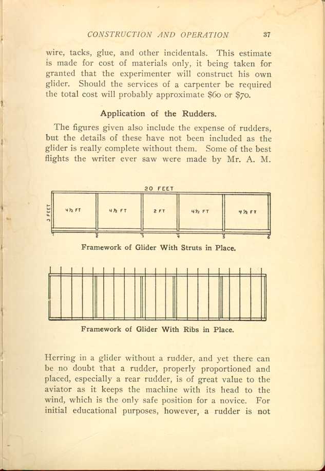
Framework of Glider With Struts in Place.
[Description: Black and white illustration: Top: diagram of glider with
struts. Bottom: diagram of glider with ribs.]
Framework of Glider With Ribs in Place.
Putting the Machine Together.
Having obtained the necessary material, the first move is to have the rib pieces steamed and curved. This curve may be slight, about 2 inches for the 4 feet. While this is being done the other parts should be carefully rounded so the square edges will be taken off. This may be done with sand paper. Next apply a coat of shellac, and when dry rub it down thoroughly with fine sand paper. When the ribs are curved treat them in the same way.
Lay two of the long horizontal frame pieces on the floor 3 feet apart. Between these place six of the strut pieces. Put one at each end, and each 4 1/2 feet put another, leaving a 2-foot space in the center. This will give you four struts 4 1/2 feet apart, and two in the center 2 feet apart, as shown in the illustration. This makes five rectangles. Be sure that the points of contact are perfect, and that the struts are exactly at right angles with the horizontal frames. This is a most important feature because if your frame "skews" or twists you cannot keep it straight in the air. Now glue the ends of the struts to the frame pieces, using plenty of glue, and nail on strips that will hold the frame in place while the glue is drying. The next day lash the joints together firmly with the shoe thread, winding it as you would to mend a broken gun stock, and over each layer put a coating of glue. This done, the other frame pieces and struts may be treated in the same way, and you will thus get the foundations for the two planes.
Another Way of Placing Struts.
In the machines built for professional use a stronger and more certain form of construction is desired. This is secured by the placing the struts for the lower plane under the frame piece, and those for the upper plane over it, allowing them in each instance to come out flush with the outer edges of the frame pieces. They are then securely fastened with a tie plate or clamp which passes over the end of the strut and is bound firmly against the surface of the frame piece by the eye bolts of the stanchion sockets.
Placing the Rib Pieces.
Take one of the frames and place on it the ribs, with the arched side
up, letting one end of the ribs come
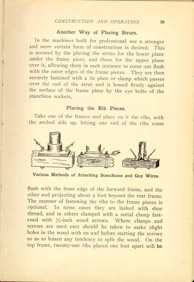
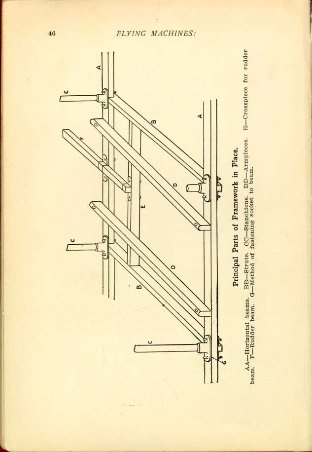
Various Methods of Attaching Stanchions and Guy Wires.
[Description: Black and white illustration: Three diagrams showing
attachment of wires.]
Joining the Two Frames.
The two frames must now be joined together. For this you will need twenty-four aluminum or iron sockets which may be purchased at a foundry or hardware shop. These sockets, as the name implies, provide a receptacle in which the end of a stanchion is firmly held, and have flanges with holes for eye-bolts which hold them firmly to the frame pieces, and also serve to hold the guy wires. In addition to these eye-bolt holes there are two others through which screws are fastened into the frame pieces. On the front frame piece of the bottom plane place six sockets, beginning at the end of the frame, and locating them exactly opposite the struts. Screw the sockets into position with wood screws, and then put the eye-bolts in place. Repeat the operation on the rear frame. Next put the sockets for the upper plane frame in place.
You are now ready to bring the two planes together. Begin by inserting the stanchions in the sockets in the lower plane. The ends may need a little rubbing with sandpaper to get them into the sockets, but care must be taken to have them fit snugly. When all the stanchions are in place on the lower plane, lift the upper plane into position, and fit the sockets over the upper ends of the stanchions.
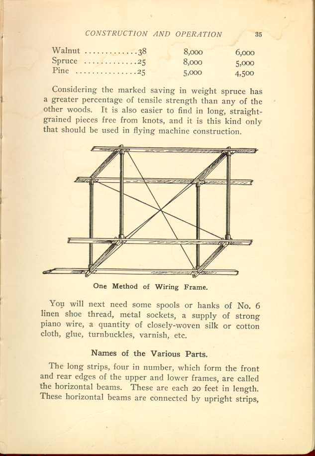
Trussing with Guy Wires.
The next move is to "tie" the frame together rigidly by the aid of guy wires. This is where the No. 12 piano wire comes in. Each rectangle formed by the struts and stanchions with the exception of the small center one, is to be wired separately as shown in the illustration. At each of the eight corners forming the rectangle the
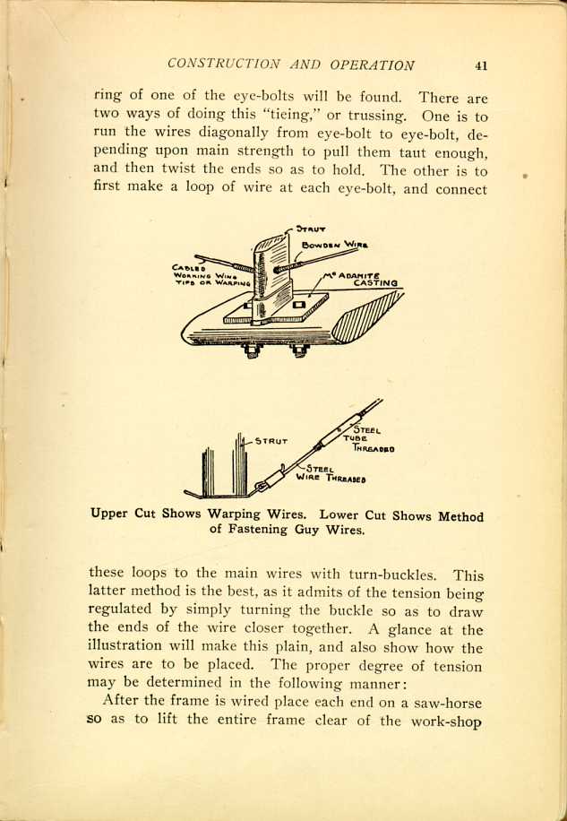
Upper Cut Shows Warping Wires. Lower Cut Shows Method of Fastening Guy Wires.
[Description: Black and white illustration: Two diagrams showing attachment of wires.]After the frame is wired place each end on a saw-horse so as to lift the entire frame clear of the work-shop
Putting on the Cloth.
We are now ready to put on the cloth covering which holds the air and makes the machine buoyant. The kind of material employed is of small account so long as it is light, strong, and wind-proof, or nearly so. Some aviators use what is called rubberized silk, others prefer balloon cloth. Ordinary muslin of good quality, treated with a coat of light varnish after it is in place, will answer all the purposes of the amateur.
Cut the cloth into strips a little over 4 feet in length. As you have 20 feet in width to cover, and the cloth is one yard wide, you will need seven strips for each plane, so as to allow for laps, etc. This will give you fourteen strips. Glue the end of each strip around the front horizontal beams of the planes, and draw each strip back, over the ribs, tacking the edges to the ribs as you go along, with small copper or brass tacks. In doing this keep the cloth smooth and stretched tight. Tacks should also be used in addition to the glue, to hold the cloth to the horizontal beams.
Next, give the cloth a coat of varnish on the clear, or upper side, and when this is dry your glider will be ready for use.
Reinforcing the Cloth.
While not absolutely necessary for amateur purposes, reinforcement of the cloth, so as to avoid any tendency to split or tear out from wind-pressure, is desirable. One
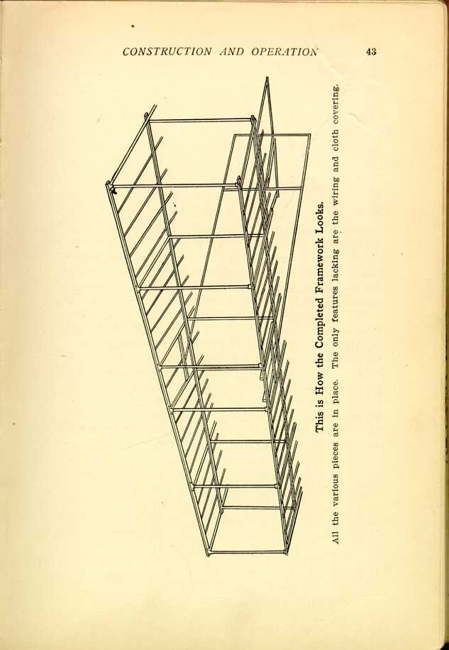
This is How the Completed Framework Looks.
All the various pieces are in place. The only features lacking are the
wiring and cloth covering.
[Description: Black and white illustration: Skeleton of glider.]
Use of Armpieces.
Should armpieces be desired, aside from those afforded by the center struts, take two pieces of spruce, 3 feet long, by 1 x 1 3/4 inches, and bolt them to the front and rear beams of the lower plane about 14 inches apart. These will be more comfortable than using the struts, as the operator will not have to spread his arms so much. In using the struts the operator, as a rule, takes hold of them with his hands, while with the armpieces, as the name implies, he places his arms over them, one of the strips coming under each armpit.
Frequently somebody asks why the ribs should be curved. The answer is easy. The curvature tends to direct the air downward toward the rear and, as the air is thus forced downward, there is more or less of an impact which assists in propelling the aeroplane upwards.
| CHAPTER V.
CONSTRUCTING A GLIDING MACHINE. Flying Machines: Construction and Operation: A Practical Book Which Shows, in Illustrations, Working Plans and Text, How to Build and Navigate the Modern Airship. | ||