|
XI
THE EDISON FEEDER SYSTEM
Edison, His Life and Inventions, vol. 2 | ||
11.
XI
THE EDISON FEEDER SYSTEM
TO quote from the preamble of the specifications of United States Patent No. 264,642, issued to Thomas A. Edison September 19, 1882: "This invention relates to a method of equalizing the tension or `pressure' of the current through an entire system of electric lighting or other translation of electric force, preventing what is ordinarily known as a `drop' in those portions of the system the more remote from the central station....''
The problem which was solved by the Edison feeder system was that relating to the equal distribution of current on a large scale over extended areas, in order that a constant and uniform electrical pressure could be maintained in every part of the distribution area without prohibitory expenditure for copper for mains and conductors.
This problem had a twofold aspect, although each side was inseparably bound up in the other. On the one hand it was obviously necessary in a lighting system that each lamp should be of standard candle-power, and capable of interchangeable use on any part of the system, giving the same degree of illumination at every point, whether near to or remote from the source of electrical energy. On the other hand, this must be accomplished by means of a system of conductors so devised and arranged that while they would insure the equal pressure thus demanded, their mass and consequent cost would not exceed the bounds of practical and commercially economical investment.
The great importance of this invention can be better understood and appreciated by a brief glance at the state of the art in 1878-79, when Edison was conducting the final series of investigations which culminated in his invention of the incandescent lamp and system of lighting. At this time, and
The earlier investigators, including those up to the period above named, thought of the problem as involving the subdivision of a fixed unit of current, which, being sufficient to cause illumination by one large lamp, might be divided into a number of small units whose aggregate light would equal the candle-power of this large lamp. It was found, however, in their experiments that the contrary effect was produced, for with every additional lamp introduced in the circuit the total candle-power decreased instead of increasing. If they were placed in series the light varied inversely as the square of the number of lamps in circuit; while if they were inserted in multiple arc, the light diminished as the cube of the number in circuit.[11.1] The idea of maintaining a constant potential and of proportioning the current to the number of lamps in circuit did not occur to most of these early investigators as a feasible method of overcoming the supposed difficulty.
It would also seem that although the general method of placing experimental lamps in multiple arc was known at this period, the idea of "drop'' of electrical pressure was imperfectly understood, if, indeed, realized at all, as a most important item to be considered in attempting the solution of the problem. As a matter of fact, the investigators preceding Edison do not seem to have conceived the idea of a "system'' at all; hence it is not surprising to find them far astray from the correct theory of subdivision of the electric current. It may easily be believed that the term "subdivision'' was a misleading one to these early experimenters. For a very short time Edison also was thus misled, but as
Generally speaking, all conductors of electricity offer more or less resistance to the passage of current through them and in the technical terminology of electrical science the word "drop'' (when used in reference to a system of distribution) is used to indicate a fall or loss of initial electrical pressure arising from the resistance offered by the copper conductors leading from the source of energy to the lamps. The result of this resistance is to convert or translate a portion of the electrical energy into another form—namely, heat, which in the conductors is useless and wasteful and to some extent inevitable in practice, but is to be avoided and remedied as far as possible.
It is true that in an electric-lighting system there is also a fall or loss of electrical pressure which occurs in overcoming the much greater resistance of the filament in an incandescent lamp. In this case there is also a translation of the energy, but here it accomplishes a useful purpose, as the energy is converted into the form of light through the incandescence of the filament. Such a conversion is called "work'' as distinguished from "drop,'' although a fall of initial electrical pressure is involved in each case.
The percentage of "drop'' varies according to the quantity of copper used in conductors, both as to cross-section and length. The smaller the cross-sectional area, the greater the percentage of drop. The practical effect of this drop would be a loss of illumination in the lamps as we go farther away from the source of energy. This may be illustrated by a simple diagram in which G is a generator, or source of energy, furnishing current at a potential or electrical pressure of 110 volts; 1 and 2 are main conductors, from which 110-volt lamps, L, are taken in derived circuits. It will be understood that the circuits represented in Fig. 1 are theoretically supposed to extend over a large area. The main conductors are sufficiently large in cross-section to offer but little resistance in those parts which are comparatively near the generator, but as the current traverses their extended length there is a gradual increase of resistance to overcome, and consequently the drop increases, as shown by the figures.
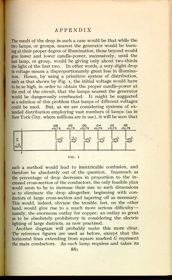
FIG. 1
[Description: Illustration of the distribution of electrical current.]Another diagram will probably make this more clear. The reference figures are used as before, except that the horizontal lines extending from square marked G represent the main conductors. As each lamp requires and takes its
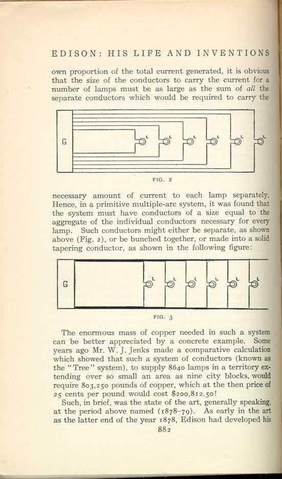
FIG. 2
[Description: Illustration of the distribution of current over separate conductors.]
FIG. 3
[Description: Illustration of a solid tapering conductor.]The enormous mass of copper needed in such a system can be better appreciated by a concrete example. Some years ago Mr. W. J. Jenks made a comparative calculation which showed that such a system of conductors (known as the "Tree'' system), to supply 8640 lamps in a territory extending over so small an area as nine city blocks, would require 803,250 pounds of copper, which at the then price of 25 cents per pound would cost $200,812.50!
Such, in brief, was the state of the art, generally speaking, at the period above named (1878-79). As early in the art as the latter end of the year 1878, Edison had developed his
His next development was the radical advancement of the state of the art to the feeder system, covered by the patent now under discussion. This invention swept away the tree and other systems, and at one bound brought into being the possibility of effectively distributing large currents over extended areas with a commercially reasonable investment for copper.
The fundamental principles of this invention were, first,
to sever entirely any direct connection of the main conductors
with the source of energy; and, second, to feed current
at a constant potential to central points in such main
conductors by means of other conductors, called "feeders,''
which were to be connected directly with the source of energy
at the central station. This idea will be made more clear by
reference to the following simple diagram, in which the same
letters are used as before, with additions:
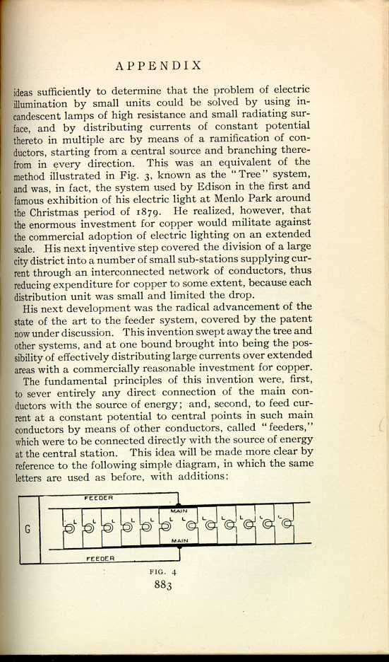
FIG. 4
[Description: Diagram illustrating the principles of the feeder system.
]
In further elucidation of the diagram, it may be considered that the mains are laid in the street along a city block, more or less distant from the station, while the feeders are connected at one end with the source of energy at the station, their other extremities being connected to the mains at central points of distribution. Of course, this system was intended to be applied in every part of a district to be supplied with current, separate sets of feeders running out from the station to the various centres. The distribution mains were to be of sufficiently large size that between their most extreme points the loss would not be more than 3 volts. Such a slight difference would not make an appreciable variation in the candle-power of the lamps.
By the application of these principles, the inevitable but useless loss, or "drop,'' required by economy might be incurred, but was localized in the feeders, where it would not affect the uniformity of illumination of the lamps in any of the circuits, whether near to or remote from the station, because any variations of loss in the feeders would not give rise to similar fluctuations in any lamp circuit. The feeders might be operated at any desired percentage of loss that would realize economy in copper, so long as they delivered current to the main conductors at the potential represented by the average voltage of the lamps.
Thus the feeders could be made comparatively small in cross-section. It will be at once appreciated that, inasmuch as the mains required to be laid only along the blocks to be lighted, and were not required to be run all the way to the central station (which might be half a mile or more away), the saving of copper by Edison's feeder system was enormous. Indeed, the comparative calculation of Mr. Jenks, above referred to, shows that to operate the same number of lights in the same extended area of territory, the feeder system would require only 128,739 pounds of copper, which, at the then price of 25 cents per pound, would cost only $39,185, or a saving of $168,627.50 for copper in this very small district of only nine blocks.
An additional illustration, appealing to the eye, is presented in the following sketch, in which the comparative masses of copper of the tree and feeder systems for carrying the same current are shown side by side:
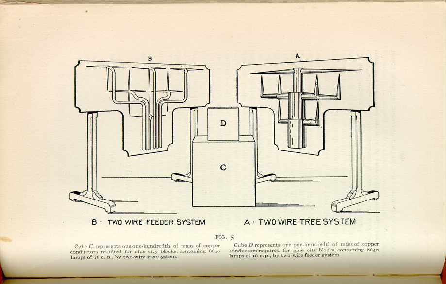
FIG 5.
B. TWO WIRE FEEDER SYSTEM A. TWO WIRE TREE SYSTEM
M. Fontaine, in his book on Electric Lighting (1877), showed that with the current of a battery composed of sixteen elements, one lamp gave an illumination equal to 54 burners; whereas two similar lamps, if introduced in parallel or multiple arc, gave the light of only 6 ½ burners in all; three lamps of only 2 burners in all; four lamps of only ¾ of one burner, and five lamps of ¼ of a burner.
|
XI
THE EDISON FEEDER SYSTEM
Edison, His Life and Inventions, vol. 2 | ||