|
II
THE QUADRUPLEX AND PHONOPLEX
Edison, His Life and Inventions, vol. 2 | ||
2.
II
THE QUADRUPLEX AND PHONOPLEX
EDISON'S work in stock printers and telegraphy had marked him as a rising man in the electrical art of the period but his invention of quadruplex telegraphy in 1874 was what brought him very prominently before the notice of the public. Duplex telegraphy, or the sending of two separate messages in opposite directions at the same time over one line was known and practiced previous to this time, but quadruplex telegraphy, or the simultaneous sending of four separate messages, two in each direction, over a single line had not been successfully accomplished, although it had been the subject of many an inventor's dream and the object of anxious efforts for many long years.
In the early part of 1873, and for some time afterward, the system invented by Joseph Stearns was the duplex in practical use. In April of that year, however, Edison took up the study of the subject and filed two applications for patents. One of these applications[2.1] embraced an invention by which two messages could be sent not only duplex, or in opposite directions as above explained, but could also be sent "diplex''—that is to say, in one direction, simultaneously, as separate and distinct messages, over the one line. Thus there was introduced a new feature into the art of multiplex telegraphy, for, whereas duplexing (accomplished by varying the strength of the current) permitted messages to be sent simultaneously from opposite stations, diplexing (achieved by also varying the direction of the current) permitted the simultaneous transmission of two messages from the same station and their separate reception at the distant station.
The quadruplex was the tempting goal toward which Edison now constantly turned, and after more than a year's strenuous work he filed a number of applications for patents in the late summer of 1874. Among them was one which was issued some years afterward as Patent No. 480,567, covering his well-known quadruplex. He had improved his own diplex, combined it with the Stearns duplex and thereby produced a system by means of which four messages could be sent over a single line at the same time, two in each direction.
As the reader will probably be interested to learn something of the theoretical principles of this fascinating invention, we shall endeavor to offer a brief and condensed explanation thereof with as little technicality as the subject will permit. This explanation will necessarily be of somewhat elementary character for the benefit of the lay reader, whose indulgence is asked for an occasional reiteration introduced for the sake of clearness of comprehension. While the apparatus and the circuits are seemingly very intricate, the principles are really quite simple, and the difficulty of comprehension is more apparent than real if the underlying phenomena are studied attentively.
At the root of all systems of telegraphy, including multiplex systems, there lies the single basic principle upon which their performance depends—namely, the obtaining of a slight mechanical movement at the more or less distant end of a telegraph line. This is accomplished through the utilization of the phenomena of electromagnetism. These phenomena are easy of comprehension and demonstration. If a rod of soft iron be wound around with a number of turns of insulated wire, and a current of electricity be sent through the wire, the rod will be instantly magnetized and will remain a magnet as long as the current flows; but when the current is cut off the magnetic effect instantly ceases. This device is known as an electromagnet, and the charging and discharging of such a magnet may, of course, be repeated indefinitely. Inasmuch as a magnet has the power of attracting to itself pieces of iron or steel, the basic importance of an electromagnet in telegraphy will be at once apparent when we consider the sounder, whose clicks are familiar to every ear. This instrument consists essentially of an electro-magnet
Passing on to the consideration of another phase of the
phenomena of electromagnetism, the reader's attention is
called to Fig. 1, in which will be seen on the left a simple
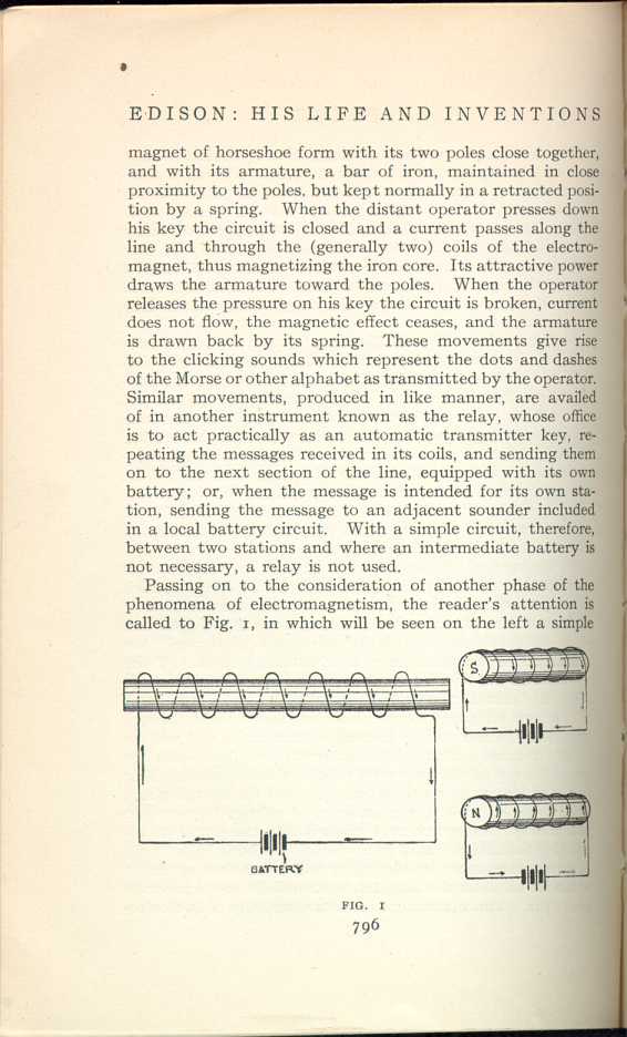
FIG. 1
[Description: Simple drawing of an electromagnet consisting of a
bar of soft iron wound around with insulated wire.]
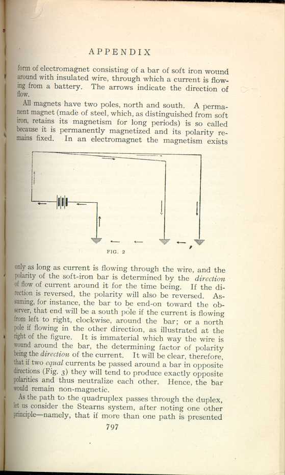
FIG. 2
[Description: Diagram of the flow of electric current, in which one pole of
the battery is connected with the earth, and from the other pole two
wires of equal resistance run to the earth.]
As the path to the quadruplex passes through the duplex, let us consider the Stearns system, after noting one other principle—namely, that if more than one path is presented
The above principles were employed in the Stearns differential duplex system in the following manner: Referring to Fig. 3, suppose a wire, A, is led from a battery around a bar of soft iron from left to right, and another wire of equal resistance and equal number of turns, B, around from right to left. The flow of current will cause two equal opposing actions to be set up in the bar; one will exactly offset the other, and no magnetic effect will be produced. A relay thus wound is known as a differential relay—more generally called a neutral relay.
The non-technical reader may wonder what use can possibly
be made of an apparently non-operative piece of apparatus.
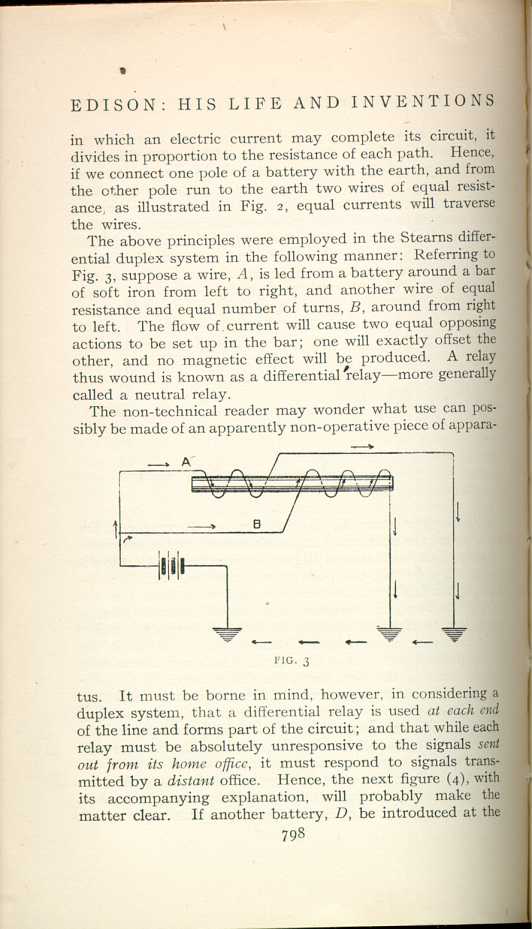
FIG. 3
[Description: Diagram of two equal currents passing around a bar in opposite
directions.]
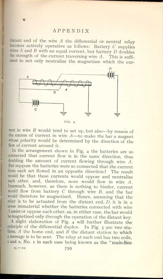
FIG. 4
[Description: Drawing of the flow of current when the batteries are connected so that the current flow is in the same direction, thus doubling the amount of current flowing through the wire.]In the arrangement shown in Fig. 4 the batteries are so connected that current flow is in the same direction, thus doubling the amount of current flowing through wire A. But suppose the batteries were so connected that the current from each set flowed in an opposite direction? The result would be that these currents would oppose and neutralize each other, and, therefore, none would flow in wire A. Inasmuch, however, as there is nothing to hinder, current would flow from battery C through wire B, and the bar would therefore be magnetized. Hence, assuming that the relay is to be actuated from the distant end, D, it is in a sense immaterial whether the batteries connected with wire A assist or oppose each other, as, in either case, the bar would be magnetized only through the operation of the distant key.
A slight elaboration of Fig. 4 will further illustrate the principle of the differential duplex. In Fig. 5 are two stations, A the home end, and B the distant station to which a message is to be sent. The relay at each end has two coils, 1 and 2, No. 1 in each case being known as the "main-line
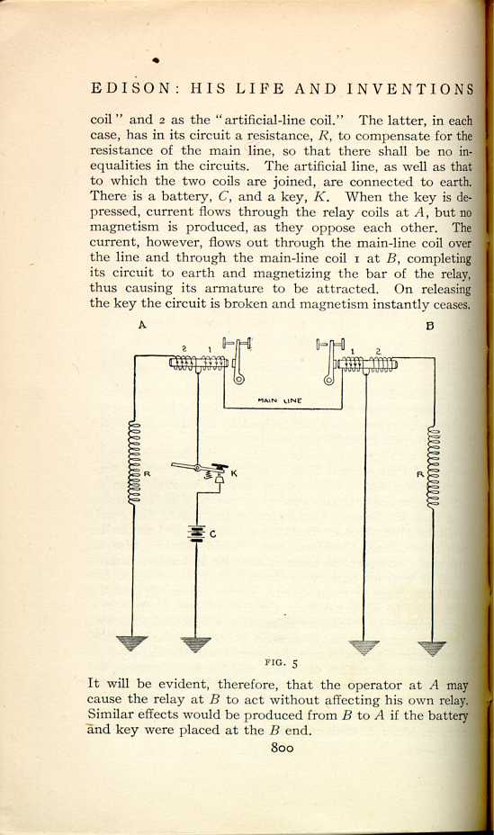
FIG. 5
[Description: Image of a cicuit.]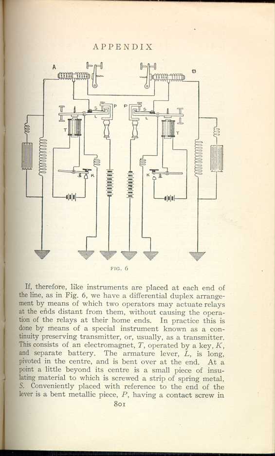
FIG. 6
[Description: Image of circuit used to illustrate the differential duplex arrangement.]If, therefore, like instruments are placed at each end of the line, as in Fig. 6, we have a differential duplex arrangement by means of which two operators may actuate relays at the ends distant from them, without causing the operation of the relays at their home ends. In practice this is done by means of a special instrument known as a continuity preserving transmitter, or, usually, as a transmitter. This consists of an electromagnet, T, operated by a key, K, and separate battery. The armature lever, L, is long, pivoted in the centre, and is bent over at the end. At a point a little beyond its centre is a small piece of insulating material to which is screwed a strip of spring metal, S. Conveniently placed with reference to the end of the lever is a bent metallic piece, P, having a contact screw in
In Fig. 6 one transmitter is shown as closed, at A, while the other one is open. From our previous illustrations and explanations it will be readily seen that, with the transmitter closed at station A, current flows via post P, through S, and to both relay coils at A, thence over the main line to main-line coil at B, and down to earth through S and the armature lever with its grounded wire. The relay at A would be unresponsive, but the core of the relay at B would be magnetized and its armature respond to signals from A. In like manner, if the transmitter at B be closed, current would flow through similar parts and thus cause the relay at A to respond. If both transmitters be closed simultaneously, both batteries will be placed to the line, which would practically result in doubling the current in each of the main-line coils, in consequence of which both relays are energized and their armatures attracted through the operation of the keys at the distant ends. Hence, two messages can be sent in opposite directions over the same line simultaneously.
The reader will undoubtedly see quite clearly from the above system, which rests upon varying the strength of the current, that two messages could not be sent in the same direction over the one line at the same time. To accomplish this object Edison introduced another and distinct feature—namely, the using of the same current, but also varying its direction of flow; that is to say, alternately reversing the polarity of the batteries as applied to the line and thus producing corresponding changes in the polarity
With this idea clearly in mind, the theory of the polarized relay, generally called "polar'' relay, as presented in the diagram (Fig. 7), will be readily understood.
A is a bar of soft iron, bent as shown, and wound around
with insulated copper wire, the ends of which are connected
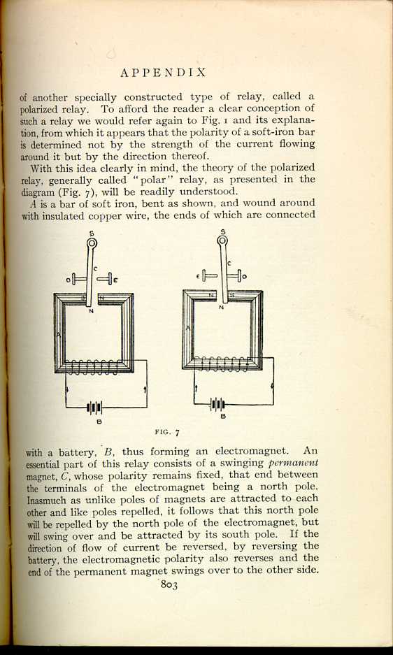
FIG. 7
[Description: Diagram illustrating the polar relay.]
Manifestly there must be provided some convenient way for rapidly transposing the direction of the current flow if such a device as the polar relay is to be used for the reception of telegraph messages, and this is accomplished by means of an instrument called a pole-changer, which consists essentially of a movable contact piece connected permanently to the earth, or grounded, and arranged to connect one or the other pole of a battery to the line and simultaneously ground the other pole. This action of the pole-changer is effected by movements of the armature of an electromagnet through the manipulation of an ordinary telegraph key by an operator at the home station, as in the operation of the "transmitter,'' above referred to.
By a combination of the neutral relay and the polar relay two operators, by manipulating two telegraph keys in the ordinary way, can simultaneously send two messages over one line in the same direction with the same current, one operator varying its strength and the other operator varying its polarity or direction of flow. This principle was covered by Edison's Patent No. 162,633, and was known as the "diplex'' system, although, in the patent referred to, Edison showed and claimed the adaptation of the principle to duplex telegraphy. Indeed, as a matter of fact, it was found that by winding the polar relay differentially and arranging the circuits and collateral appliances appropriately, the polar duplex system was more highly efficient than the neutral system, and it is extensively used to the present day.
Thus far we have referred to two systems, one the neutral or differential duplex, and the other the combination of the neutral and polar relays, making a diplex system. By one of these two systems a single wire could be used for sending two messages in opposite directions, and by the other in the same direction or in opposite directions. Edison followed up his work on the diplex and combined the two
Our explanation has merely aimed to show the underlying phenomena and principles in broad outline without entering into more detail than was deemed absolutely necessary. It should be stated, however, that between the outline and the filling in of the details there was an enormous amount of hard work, study, patient plodding, and endless experiments before Edison finally perfected his quadruplex system in the year 1874.
If it were attempted to offer here a detailed explanation of the varied and numerous operations of the quadruplex, this article would assume the proportions of a treatise. An idea of their complexity may be gathered from the following, which is quoted from American Telegraphy and Encyclopedia of the Telegraph, by William Maver, Jr.:
"It may well be doubted whether in the whole range of applied electricity there occur such beautiful combinations, so quickly made, broken up, and others reformed, as in the operation of the Edison quadruplex. For example, it is quite demonstrable that during the making of a simple dash of the Morse alphabet by the neutral relay at the home
We present a diagrammatic illustration of the Edison quadruplex, battery key system, in Fig. 8, and refer the reader to the above or other text-books if he desires to make a close study of its intricate operations. Before finally dismissing the quadruplex, and for the benefit of the inquiring reader who may vainly puzzle over the intricacies of the circuits shown in Fig. 8, a hint as to an essential difference between the neutral relay, as used in the duplex and as used in the quadruplex, may be given. With the duplex, as we have seen, the current on the main line is changed in strength only when both keys at opposite stations are closed together, so that a current due to both batteries flows over the main line. When a single message is sent from one station to the other, or when both stations are sending messages that do not conflict, only one battery or the other is connected to the main line; but with the quadruplex, suppose one of the operators, in New York for instance, is sending reversals of current to Chicago; we can readily see how these changes in polarity will operate the polar relay at the distant station, but why will they not also operate the neutral relay at the distant station as well? This difficulty was solved by dividing the battery at each station into two unequal parts, the smaller battery being always in circuit with the pole-changer ready to have its polarity reversed on the main line to operate the distant polar relay, but the spring retracting the
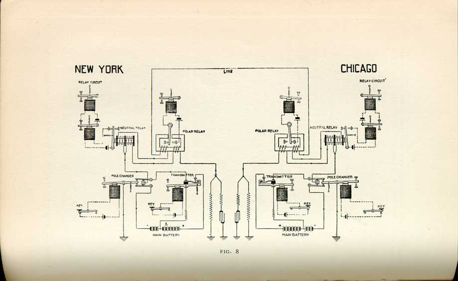 [Description: Diagram of the Edison quadraplex battery
key system.]
[Description: Diagram of the Edison quadraplex battery
key system.]Edison made another notable contribution to multiplex telegraphy some years later in the Phonoplex. The name suggests the use of the telephone, and such indeed is the case. The necessity for this invention arose out of the problem of increasing the capacity of telegraph lines employed in "through'' and "way'' service, such as upon railroads. In a railroad system there are usually two terminal stations and a number of way stations. There is naturally much intercommunication, which would be greatly curtailed by a system having the capacity of only a single message at a time. The duplexes above described could not
The system is a combination of telegraphic apparatus and telephone receiver, although in this case the latter instrument is not used in the generally understood manner. It is well known that the diaphragm of a telephone vibrates with the fluctuations of the current energizing the magnet beneath it. If the make and break of the magnetizing current be rapid, the vibrations being within the limits of the human ear, the diaphragm will produce an audible sound; but if the make and break be as slow as with ordinary Morse transmission, the diaphragm will be merely flexed and return to its original form without producing a sound. If, therefore, there be placed in the same circuit a regular telegraph relay and a special telephone, an operator may, by manipulating a key, operate the relay (and its sounder) without producing a sound in the telephone, as the makes and breaks of the key are far below the limit of audibility. But if through the same circuit, by means of another key suitably connected there is sent the rapid changes in current from an induction-coil, it will cause a series of loud clicks in the telephone, corresponding to the signals transmitted; but this current is too weak to affect the telegraph relay. It will be seen, therefore, that this method of duplexing is practiced, not by varying the strength or polarity, but by sending two kinds of current over the wire. Thus, two sets of Morse signals can be transmitted by two operators over one line at the same time without interfering with each other, and not only between terminal offices, but also between a terminal office and any intermediate office, or between two intermediate offices alone.
Many of the illustrations in this article are reproduced from American Telegraphy and Encyclopedia of the Telegraph, by William Maver, Jr., by permission of Maver Publishing Company, New York.
|
II
THE QUADRUPLEX AND PHONOPLEX
Edison, His Life and Inventions, vol. 2 | ||