|
V
THE ELECTROMOTOGRAPH
Edison, His Life and Inventions, vol. 2 | ||
5.
V
THE ELECTROMOTOGRAPH
IN solving a problem that at the time was thought to be insurmountable, and in the adaptability of its principles to the successful overcoming of apparently insuperable difficulties subsequently arising in other lines of work, this invention is one of the most remarkable of the many that Edison has made in his long career as an inventor.
The object primarily sought to be accomplished was the repeating of telegraphic signals from a distance without the aid of a galvanometer or an electromagnetic relay, to overcome the claims of the Page patent referred to in the preceding narrative. This object was achieved in the device described in Edison's basic patent No. 158,787, issued January 19, 1875, by the substitution of friction and anti-friction for the presence and absence of magnetism in a regulation relay.
It may be observed, parenthetically, for the benefit of the lay reader, that in telegraphy the device known as the relay is a receiving instrument containing an electromagnet adapted to respond to the weak line-current. Its armature moves in accordance with electrical impulses, or signals, transmitted from a distance, and, in so responding, operates mechanically to alternately close and open a separate local circuit in which there is a sounder and a powerful battery. When used for true relaying purposes the signals received from a distance are in turn repeated over the next section of the line, the powerful local battery furnishing current for this purpose. As this causes a loud repetition of the original signals, it will be seen that relaying is an economic method of extending a telegraph circuit beyond the natural limits of its battery power.
At the time of Edison's invention, as related in Chapter
Edison's electromotograph comprised an ingeniously arranged apparatus in which two surfaces, normally in contact with each other, were caused to alternately adhere by friction or slip by reason of electrochemical decomposition. One of these surfaces consisted of a small drum or cylinder of chalk, which was kept in a moistened condition with a suitable chemical solution, and adapted to revolve continuously by clockwork. The other surface consisted of a small pad which rested with frictional pressure on the periphery of the drum. This pad was carried on the end of a vibrating arm whose lateral movement was limited between two adjustable points. Normally, the frictional pressure between the drum and pad would carry the latter with the former as it revolved, but if the friction were removed a spring on the end of the vibrator arm would draw it back to its starting-place.
In practice, the chalk drum was electrically connected with one pole of an incoming telegraph circuit, and the vibrating arm and pad with the other pole. When the drum rotated, the friction of the pad carried the vibrating arm forward, but an electrical impulse coming over the line would decompose the chemical solution with which the drum was moistened, causing an effect similar to lubrication, and thus allowing the pad to slip backward freely in response to the pull of its retractile spring. The frictional movements of the pad with the drum were comparatively long or short, and corresponded with the length of the impulses sent in over
This brings us to the gist of the ingenious way in which
Edison substituted the action of electrochemical decomposition
for that of the electromagnet to operate a relay.
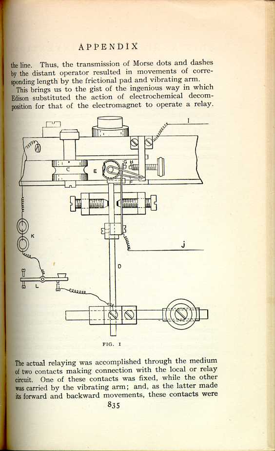
FIG. 1
[Description: Diagram of electromotograph.]
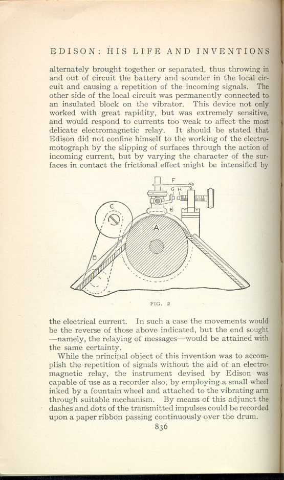
FIG. 2
[Description: Diagram of electromotograph.]While the principal object of this invention was to accomplish the repetition of signals without the aid of an electromagnetic relay, the instrument devised by Edison was capable of use as a recorder also, by employing a small wheel inked by a fountain wheel and attached to the vibrating arm through suitable mechanism. By means of this adjunct the dashes and dots of the transmitted impulses could be recorded upon a paper ribbon passing continuously over the drum.
The electromotograph is shown diagrammatically in Figs. 1 and 2, in plan and vertical section respectively. The reference letters in each case indicate identical parts: A being the chalk drum, B the paper tape, C the auxiliary cylinder, D the vibrating arm, E the frictional pad, F the spring, G and H the two contacts, I and J the two wires leading to local circuit, K a battery, and L an ordinary telegraph key. The two last named, K and L, are shown to make the sketch complete but in practice would be at the transmitting end, which might be hundreds of miles away. It will be understood, of course, that the electromotograph is a receiving and relaying instrument.
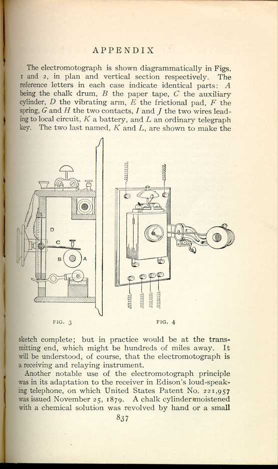
FIG. 3
[Description: Diagram of loud-speaking telephone.
]

FIG. 4
[Description: Diagram of loud-speaking telephone.]
The loud-speaking telephone is shown in section, diagrammatically, in the sketch (Fig. 3), in which A is the chalk cylinder mounted on a shaft, B. The palladium-faced pen or spring, C, is connected to diaphragm D. The instrument in its commercial form is shown in Fig. 4.
|
V
THE ELECTROMOTOGRAPH
Edison, His Life and Inventions, vol. 2 | ||