|
CHAPTER IV
THE PROPELLER, OR "AIR-SCREW"
The Aeroplane Speaks | ||
4.
CHAPTER IV
THE PROPELLER, OR "AIR-SCREW"
The sole object of the propeller is to translate the power of the engine into thrust.
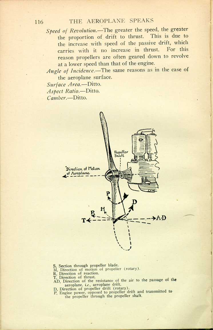
The propeller screws through the air, and its blades, being set at an angle inclined to the direction of motion, secure a reaction, as in the case of the aeroplane's lifting surface.
This reaction may be conveniently divided into two component parts or values, namely, Thrust and Drift (see illustration overleaf).
The Thrust is opposed to the Drift of the aeroplane, and must be equal and opposite to it at flying speed. If it falls off in power, then the flying speed must decrease to a velocity, at which the aeroplane drift equals the decreased thrust.
The Drift of the propeller may be conveniently divided into the following component values:
Active Drift, produced by the useful thrusting part of the propeller.
Passive Drift, produced by all the rest of the propeller, i.e., by its detrimental surface.
Skin Friction, produced by the friction of the air with roughnesses of surface.
Eddies attending the movement of the air caused by the action of the propeller.
Cavitation (very marked at excessive speed of revolution). A tendency of the propeller to produce a cavity or semi-vacuum in which it revolves, the thrust decreasing with increase of speed and cavitation.
Thrust-Drift Ratio.—The proportion of thrust to drift is of paramount importance, for it expresses the efficiency of the propeller. It is affected by the following factors:
Angle of Incidence.—The same reasons as in the case of the aeroplane surface.
Surface Area.—Ditto.
Aspect Ratio.—Ditto.
Camber.—Ditto.
In addition to the above factors there are, when it comes to actually designing a propeller, mechanical difficulties to consider. For instance, the blades must be of a certain strength and consequent thickness. That, in itself, limits the aspect ratio, for it will necessitate a chord long enough in proportion to the thickness to make a good camber possible. Again, the diameter of the propeller must be limited, having regard to the fact that greater diameters than those used to-day would not only result in excessive weight of construction, but would also necessitate a very high undercarriage to keep the propeller off the ground, and such undercarriage would not only produce excessive drift, but would also tend to make the aeroplane stand on its nose when alighting. The latter difficulty cannot be overcome by mounting the propeller higher, as the centre of its thrust must be approximately coincident with the centre of aeroplane drift.
MAINTENANCE OF EFFICIENCY.
The following conditions must be observed:
1. Pitch Angle.—The angle, at any given point on the propeller, at which the blade is set is known as the pitch angle, and it must be correct to half a degree if reasonable efficiency is to be maintained.
This angle secures the "pitch," which is the distance the propeller advances during one revolution, supposing the air to be solid. The air, as a matter of fact, gives back to the thrust of the blades just as the pebbles slip back as one ascends a shingle beach. Such "give-back" is known as Slip. If a propeller has a pitch of, say, 10 feet, but actually advances, say, only 8 feet owing to slip, then it will be said to possess 20 per cent. slip.
Thus, the pitch must equal the flying speed of the aeroplane plus the slip of the propeller. For example, let us find the pitch of a propeller, given the following conditions:
- Flying speed .............. 70 miles per hour.
- Propeller revolutions ..... 1,200 per minute.
- Slip ...................... 15 per cent.
First find the distance in feet the aeroplane will travel forward in one minute. That is—
 [Description:
Equation: 369,600 ft./60 min.=6,160 ft./min.
]
[Description:
Equation: 369,600 ft./60 min.=6,160 ft./min.
]
Now divide the feet per minute by the propeller revolutions per minute, add 15 per cent. for the slip, and the result will be the propeller pitch:
 [Description:
Equation: 6,160/1,200 + 15% = 5 ft. 1-3/5 in.
]
[Description:
Equation: 6,160/1,200 + 15% = 5 ft. 1-3/5 in.
]
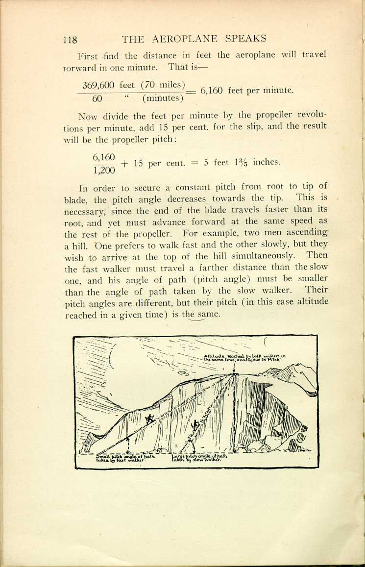
In order to secure a constant pitch from root to tip of blade, the pitch angle decreases towards the tip. This is necessary, since the end of the blade travels faster than its root, and yet must advance forward at the same speed as the rest of the propeller. For example, two men ascending a hill. One prefers to walk fast and the other slowly, but they wish to arrive at the top of the hill simultaneously. Then the fast walker must travel a farther distance than the slow one, and his angle of path (pitch angle) must be smaller than the angle of path taken by the slow walker. Their pitch angles are different, but their pitch (in this case altitude reached in a given time) is the same.
 [Description:
Illustration of two hikers climbing a mountain at different angles of pitch.
]
[Description:
Illustration of two hikers climbing a mountain at different angles of pitch.
]
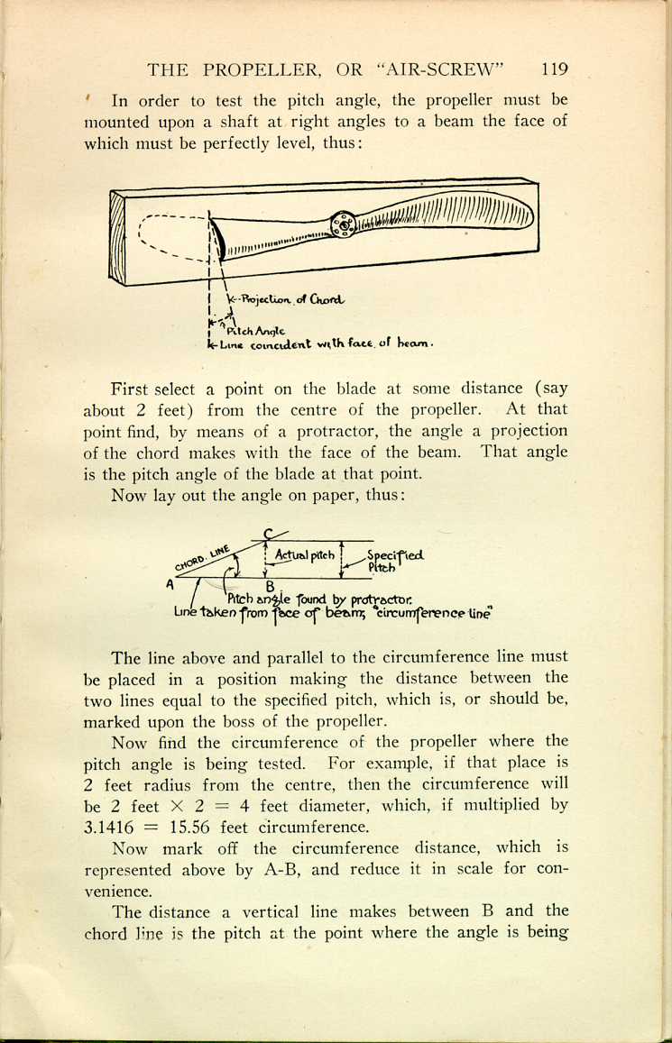
In order to test the pitch angle, the propeller must be mounted upon a shaft at right angles to a beam the face of which must be perfectly level, thus:
 [Description:
Diagram of a propeller, with the pitch angle labeled.
]
[Description:
Diagram of a propeller, with the pitch angle labeled.
]
First select a point on the blade at some distance (say about 2 feet) from the centre of the propeller. At that point find, by means of a protractor, the angle a projection of the chord makes with the face of the beam. That angle is the pitch angle of the blade at that point.
Now lay out the angle on paper, thus:
 [Description:
Diagram of the pitch angle.
]
[Description:
Diagram of the pitch angle.
]
The line above and parallel to the circumference line must be placed in a position making the distance between the two lines equal to the specified pitch, which is, or should be, marked upon the boss of the propeller.
Now find the circumference of the propeller where the pitch angle is being tested. For example, if that place is 2 feet radius from the centre, then the circumference will be 2 feet X 2 = 4 feet diameter, which, if multiplied by 3.1416 = 15.56 feet circumference.
Now mark off the circumference distance, which is represented above by A-B, and reduce it in scale for convenience.
The distance a vertical line makes between B and the chord dine is the pitch at the point where the angle is being
The propeller should be tested at several points, about a foot apart, on each blade; and the diagram, provided the propeller is not faulty, will then look like this:
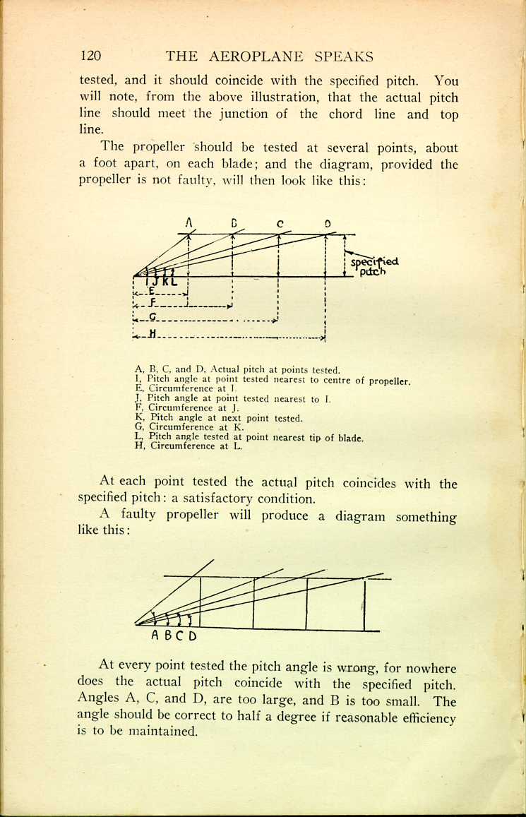
At each point tested the actual pitch coincides with the specified pitch: a satisfactory condition.
A faulty propeller will produce a diagram something like this:
 [Description:
Diagram of various pitch angles for a faulty propeller.
]
[Description:
Diagram of various pitch angles for a faulty propeller.
]
At every point tested the pitch angle is wrong, for nowhere does the actual pitch coincide with the specified pitch. Angles A, C, and D, are too large, and B is too small. The angle should be correct to half a degree if reasonable efficiency is to be maintained.
A fault in the pitch angle may be due to (1) faulty manufacture, (2) distortion, or (3) the shaft hole through the boss being out of position.
2. Straightness.—To test for straightness the propeller must be mounted upon a shaft. Now bring the tip of one blade round to graze some fixed object. Mark the point it grazes. Now bring the other tip round, and it should come within 1/8 inch of the mark. If it does not do so, it is due to (1) faulty manufacture, (2) distortion, or (3) to the hole through the boss being out of position.
3. Length.—The blades should be of equal length to 1/16 inch.
4. Balance.—The usual method of testing a propeller for balance is as follows: Mount it upon a shaft, which must be on ball-bearings. Place the propeller in a horizontal position, and it should remain in that position. If a weight of a trifle over an ounce placed in a bolt-hole on one side of the boss fails to disturb the balance, then the propeller is usually regarded as unfit for use.
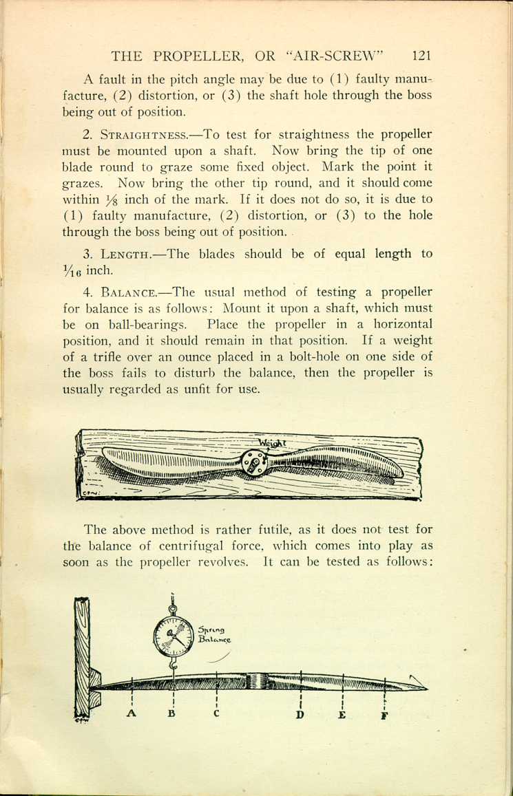 [Description:
Illustration of a propeller with the weight labeled.
]
[Description:
Illustration of a propeller with the weight labeled.
]
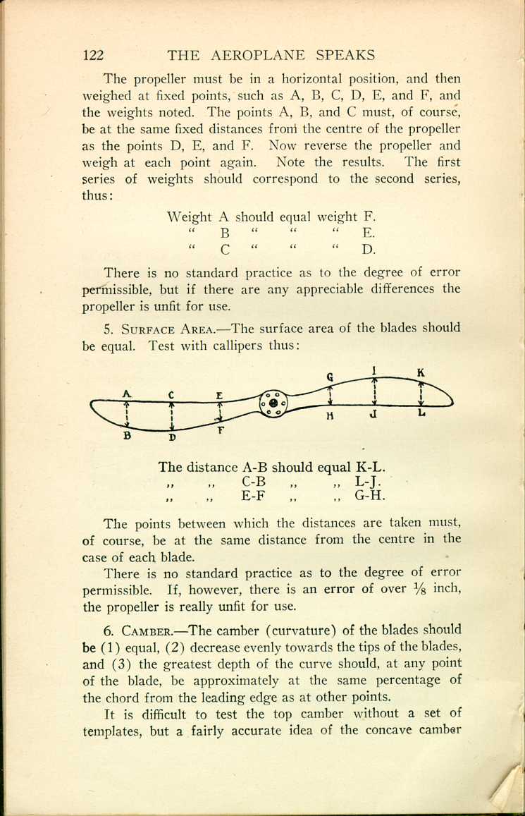
The above method is rather futile, as it does not test for the balance of centrifugal force, which comes into play as soon as the propeller revolves. It can be tested as follows:
 [Description:
Diagram showing how to test the propeller with a spring balance.
]
[Description:
Diagram showing how to test the propeller with a spring balance.
]
The propeller must be in a horizontal position, and then weighed at fixed points, such as A, B, C, D, E, and F, and the weights noted. The points A, B, and C must, of course, be at the same fixed distances from the centre of the propeller as the points D, E, and F. Now reverse the propeller and weigh at each point again. Note the results. The first series of weights should correspond to the second series, thus:
| Weight A should equal weight F. |
| " B " " " E. |
| " C " " " D. |
There is no standard practice as to the degree of error permissible, but if there are any appreciable differences the propeller is unfit for use.
5. Surface Area.—The surface area of the blades should be equal. Test with calipers thus:
 [Description:
Diagram of a propeller, showing various surface area measurements.
]
[Description:
Diagram of a propeller, showing various surface area measurements.
]
| The distance A-B should equal K-L. |
| " " C-B " " L-J. |
| " " E-F " " G-H. |
The points between which the distances are taken must, of course, be at the same distance from the centre in the case of each blade.
There is no standard practice as to the degree of error permissible. If, however, there is an error of over 1/8 inch, the propeller is really unfit for use.
6. Camber.—The camber (curvature) of the blades should be (1) equal, (2) decrease evenly towards the tips of the blades, and (3) the greatest depth of the curve should, at any point of the blade, be approximately at the same percentage of the chord from the leading edge as at other points.
It is difficult to test the top camber without a set of templates, but a fairly accurate idea of the concave camber
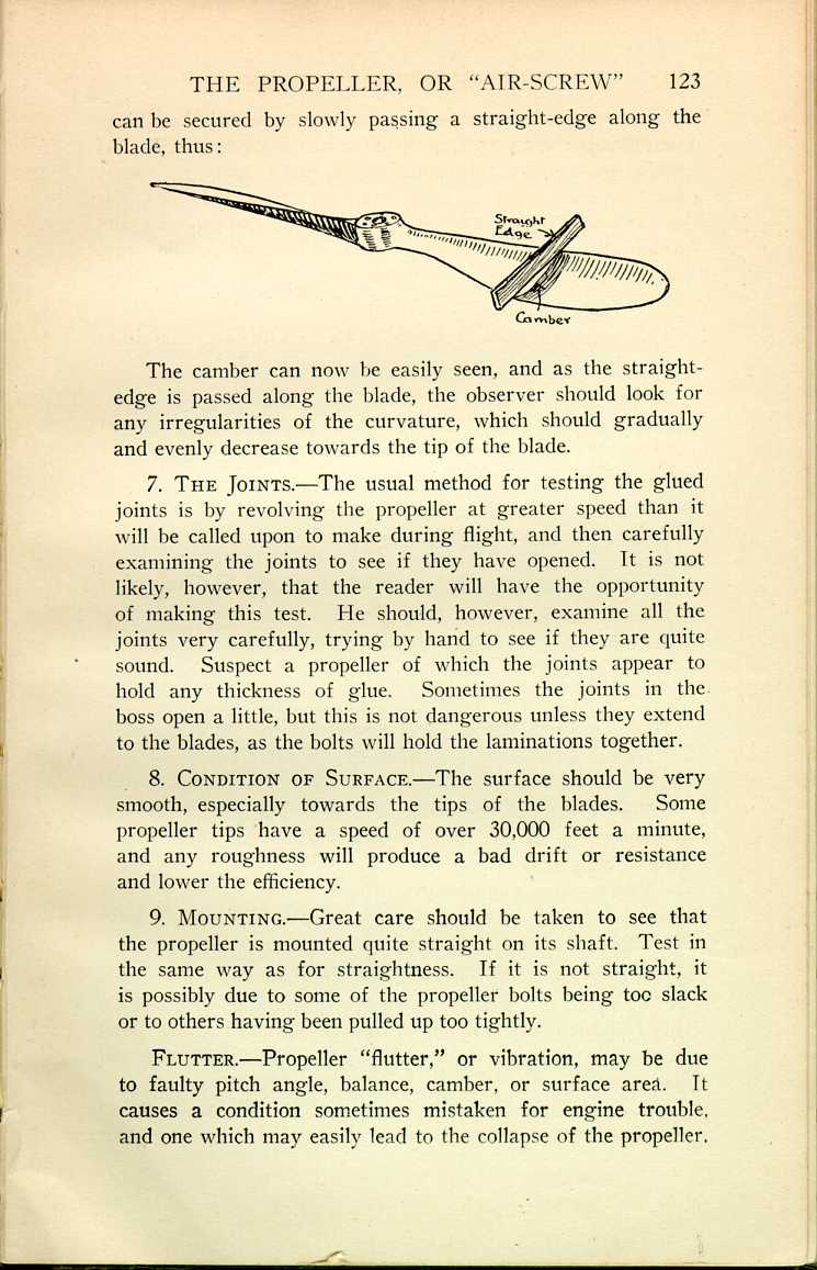 [Description:
Diagram of a propeller, with the camber measured against a straight-edge.
]
[Description:
Diagram of a propeller, with the camber measured against a straight-edge.
]
The camber can now be easily seen, and as the straight-edge is passed along the blade, the observer should look for any irregularities of the curvature, which should gradually and evenly decrease towards the tip of the blade.
7. The Joints.—The usual method for testing the glued joints is by revolving the propeller at greater speed than it will be called upon to make during flight, and then carefully examining the joints to see if they have opened. It is not likely, however, that the reader will have the opportunity of making this test. He should, however, examine all the joints very carefully, trying by hand to see if they are quite sound. Suspect a propeller of which the joints appear to hold any thickness of glue. Sometimes the joints in the boss open a little, but this is not dangerous unless they extend to the blades, as the bolts will hold the laminations together.
8. Condition of Surface.—The surface should be very smooth, especially towards the tips of the blades. Some propeller tips have a speed of over 30,000 feet a minute, and any roughness will produce a bad drift or resistance and lower the efficiency.
9. Mounting.—Great care should be taken to see that the propeller is mounted quite straight on its shaft. Test in the same way as for straightness. If it is not straight, it is possibly due to some of the propeller bolts being too slack or to others having been pulled up too tightly.
Flutter.—Propeller "flutter," or vibration, may be due to faulty pitch angle, balance, camber, or surface area. It causes a condition sometimes mistaken for engine trouble, and one which may easily lead to the collapse of the propeller.
Care of Propellers.—The care of propellers is of the greatest importance, as they become distorted very easily.
1. Do not store them in a very damp or a very dry place.
2. Do not store them where the sun will shine upon them.
3. Never leave them long in a horizontal position or leaning up against a wall.
4. They should be hung on horizontal pegs, and the position of the propellers should be vertical.
If the points I have impressed upon you in these notes are not attended to, you may be sure of the following results:
1. Lack of efficiency, resulting in less aeroplane speed and climb than would otherwise be the case.
2. Propeller "flutter" and possible collapse.
3. A bad stress upon the propeller shaft and its bearings.
Tractor.—A propeller mounted in front of the main surface.
Pusher.—A propeller mounted behind the main surface.
Four-Bladed Propellers.—Four-bladed propellers are suitable only when the pitch is comparatively large.
For a given pitch, and having regard to "interference," they are not so efficient as two-bladed propellers.
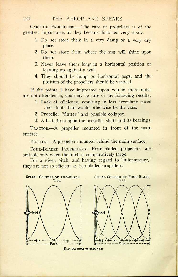
The smaller the pitch, the less the "gap," i.e., the distance, measured in the direction of the thrust, between the spiral courses of the blades (see illustration on preceding page).
If the gap is too small, then the following blade will engage air which the preceding blade has put into motion, with the result that the following blade will not secure as good a reaction as would otherwise be the case. It is very much the same as in the case of the aeroplane gap.
For a given pitch, the gap of a four-bladed propeller is only half that of a two-bladed one. Therefore the four-bladed propeller is only suitable for large pitch, as such pitch produces spirals with a large gap, thus offsetting the decrease in gap caused by the numerous blades.
The greater the speed of rotation, the less the pitch for a given aeroplane speed. Then, in order to secure a large pitch and consequently a good gap, the four-bladed propeller is usually geared to rotate at a lower speed than would be the case if directly attached to the engine crank-shaft.
|
CHAPTER IV
THE PROPELLER, OR "AIR-SCREW"
The Aeroplane Speaks | ||