|
CHAPTER I
FLIGHT
The Aeroplane Speaks | ||
1.
CHAPTER I
FLIGHT
Air has weight (about 13 cubic feet = 1 lb.), inertia, and momentum. It therefore obeys Newton's laws[1] and resists movement. It is that resistance or reaction which makes flight possible.
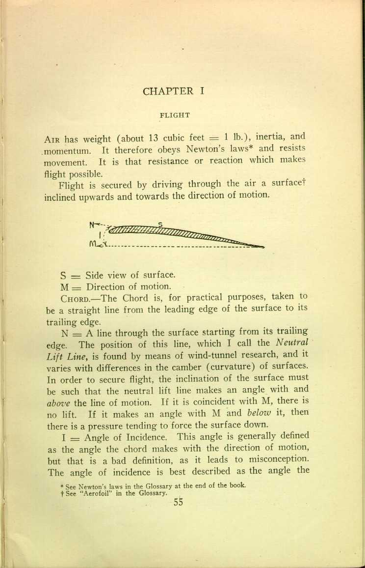
Flight is secured by driving through the air a surface[2] inclined upwards and towards the direction of motion.
 [Description:
Diagram representing an inclined surface.
]
[Description:
Diagram representing an inclined surface.
]
S = Side view of surface.
M = Direction of motion.
Chord.—The Chord is, for practical purposes, taken to be a straight line from the leading edge of the surface to its trailing edge.
N = A line through the surface starting from its trailing edge. The position of this line, which I call the Neutral Lift Line, is found by means of wind-tunnel research, and it varies with differences in the camber (curvature) of surfaces. In order to secure flight, the inclination of the surface must be such that the neutral lift line makes an angle with and above the line of motion. If it is coincident with M, there is no lift. If it makes an angle with M and below it, then there is a pressure tending to force the surface down.
I = Angle of Incidence. This angle is generally defined as the angle the chord makes with the direction of motion, but that is a bad definition, as it leads to misconception. The angle of incidence is best described as the angle the
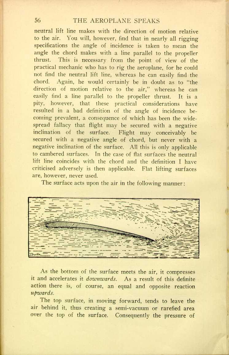
The surface acts upon the air in the following manner:
 [Description:
Illustration showing how the surface acts upon the air.
]
[Description:
Illustration showing how the surface acts upon the air.
]
As the bottom of the surface meets the air, it compresses it and accelerates it downwards. As a result of this definite action there is, of course, an equal and opposite reaction upwards.
The top surface, in moving forward, tends to leave the air behind it, thus creating a semi-vacuum or rarefied area over the top of the surface. Consequently the pressure of
The reaction increases approximately as the square of the velocity. It is the result of (1) the mass of air engaged, and (2) the velocity and consequent force with which the surface engages the air. If the reaction was produced by only one of those factors it would increase in direct proportion to the velocity, but, since it is the product of both factors, it increases as V2.
Approximately three-fifths of the reaction is due to the decrease of density (and consequent decrease of downward pressure) on the top of the surface; and only some two-fifths is due to the upward reaction secured by the action of the bottom surface upon the air. A practical point in respect of this is that, in the event of the fabric covering the surface getting into bad condition, it is more likely to strip off the top than off the bottom.
 [Description:
Diagram of the forces of lift, drift, reaction, etc. upon a surface.
]
[Description:
Diagram of the forces of lift, drift, reaction, etc. upon a surface.
]
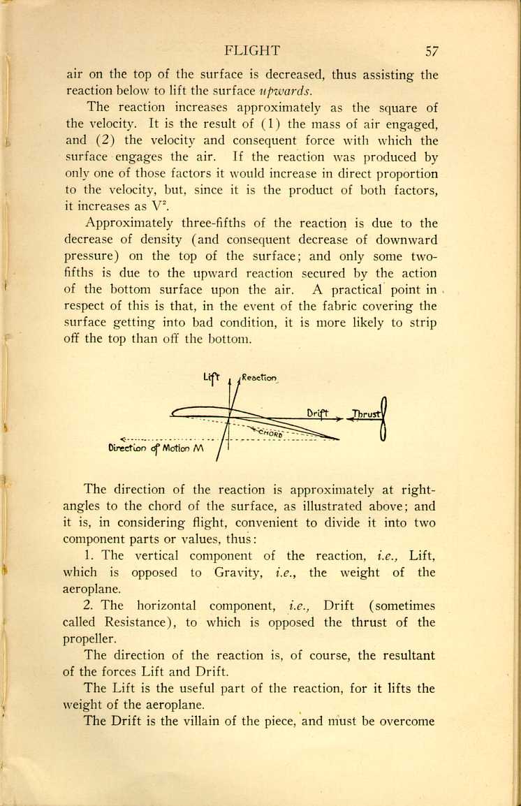
The direction of the reaction is approximately at right-angles to the chord of the surface, as illustrated above; and it is, in considering flight, convenient to divide it into two component parts or values, thus:
1. The vertical component of the reaction, i.e., Lift, which is opposed to Gravity, i.e., the weight of the aeroplane.
2. The horizontal component, i.e., Drift (sometimes called Resistance), to which is opposed the thrust of the propeller.
The direction of the reaction is, of course, the resultant of the forces Lift and Drift.
The Lift is the useful part of the reaction, for it lifts the weight of the aeroplane.
The Drift is the villain of the piece, and must be overcome
Drift.—The drift of the whole aeroplane (we have considered only the lifting surface heretofore) may be conveniently divided into three parts, as follows:
Active Drift, which is the drift produced by the lifting surfaces.
Passive Drift, which is the drift produced by all the rest of the aeroplane—the struts, wires, fuselage, under-carriage, etc., all of which is known as "detrimental surface."
Skin Friction, which is the drift produced by the friction of the air with roughnesses of surface. The latter is practically negligible having regard to the smooth surface of the modern aeroplane, and its comparatively slow velocity compared with, for instance, the velocity of a propeller blade.
Lift-Drift Ratio.—The proportion of lift to drift is known as the lift-drift ratio, and is of paramount importance, for it expresses the efficiency of the aeroplane (as distinct from engine and propeller). A knowledge of the factors governing the lift-drift ratio is, as will be seen later, an absolute necessity to anyone responsible for the rigging of an aeroplane, and the maintenance of it in an efficient and safe condition.
Those factors are as follows:
1. Velocity.—The greater the velocity the greater the proportion of drift to lift, and consequently the less the efficiency. Considering the lifting surfaces alone, both the lift and the (active) drift, being component parts of the reaction, increase as the square of the velocity, and the efficiency remains the same at all speeds. But, considering the whole aeroplane, we must remember the passive drift. It also increases as the square of the velocity (with no attendant lift), and, adding itself to the active drift, results in increasing the proportion of total drift (active + passive) to lift.
But for the increase in passive drift the efficiency
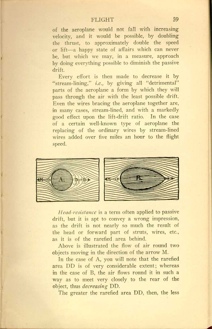
Every effort is then made to decrease it by "stream-lining," i.e., by giving all "detrimental" parts of the aeroplane a form by which they will pass through the air with the least possible drift. Even the wires bracing the aeroplane together are, in many cases, stream-lined, and with a markedly good effect upon the lift-drift ratio. In the case of a certain well-known type of aeroplane the replacing of the ordinary wires by stream-lined wires added over five miles an hour to the flight speed.
 [Description:
Diagram showing the effect of streamlining.
]
[Description:
Diagram showing the effect of streamlining.
]
Head-resistance is a term often applied to passive drift, but it is apt to convey a wrong impression, as the drift is not nearly so much the result of the head or forward part of struts, wires, etc., as it is of the rarefied area behind.
Above is illustrated the flow of air round two objects moving in the direction of the arrow M.
In the case of A, you will note that the rarefied area DD is of very considerable extent; whereas in the case of B, the air flows round it in such a way as to meet very closely to the rear of the object, thus decreasing DD.
The greater the rarefied area DD. then, the less
The "fineness" of the stream-line shape, i.e., the proportion of length to width, is determined by the velocity—the greater the velocity, the greater the fineness. The best degree of fineness for any given velocity is found by means of wind-tunnel research.
The practical application of all this is, from a rigging point of view, the importance of adjusting all stream-line parts to be dead-on in the line of flight, but more of that later on.
2. Angle of Incidence.—The most efficient angle of incidence varies with the thrust at the disposal of the designer, the weight to be carried, and the climb-velocity ratio desired.
The best angles of incidence for these varying factors are found by means of wind-tunnel research and practical trial and error. Generally speaking, the greater the velocity the smaller should be the angle of incidence, in order to preserve a clean, stream-line shape of rarefied area and freedom from eddies. Should the angle be too great for the velocity, then the rarefied area becomes of irregular shape with attendant turbulent eddies. Such eddies possess no lift value, and since it has taken power to produce them, they represent drift and adversely affect the lift-drift ratio.
From a rigging point of view, one must presume that every standard aeroplane has its lifting surface set at the most efficient angle, and the practical application of all this is in taking the greatest possible care to rig the surface at the correct angle and to maintain it at such angle. Any deviation will adversely affect the lift-drift ratio, i.e., the efficiency.
3. Camber.—(Refer to the second illustration in this chapter.) The lifting surfaces are cambered, i.e., curved, in order to decrease the horizontal component of the reaction, i.e., the drift.
The bottom camber: If the bottom of the surface was flat, every particle of air meeting it would do so with a shock, and such shock would produce a very considerable horizontal reaction or drift. By curving it such shock is diminished, and the curve should be such as to produce a uniform (not necessarily constant) acceleration and compression of the air from the leading edge to the trailing edge. Any unevenness in the acceleration and compression of the air produces drift.
The top camber: If this was flat it would produce a rarefied area of irregular shape. I have already explained the bad effect this has upon the lift-drift ratio. The top surface is then curved to produce a rarefied area the shape of which shall be as stream-line and free from attendant eddies as possible.
The camber varies with the angle of incidence, the velocity, and the thickness of the surface. Generally speaking, the greater the velocity, the less the camber and angle of incidence. With infinite velocity the surface would be set at no angle of incidence (the neutral lift line coincident with the direction of motion relative to the air), and would be, top and bottom, of pure streamline form—i.e., of infinite fineness. This is, of course, carrying theory to absurdity as the surface would then cease to exist.
The best cambers for varying velocities, angles of incidence, and thicknesses of surface, are found by means of wind-tunnel research. The practical application of all this is in taking the greatest care to prevent the surface from becoming distorted and thus spoiling the camber and consequently the lift-drift ratio.
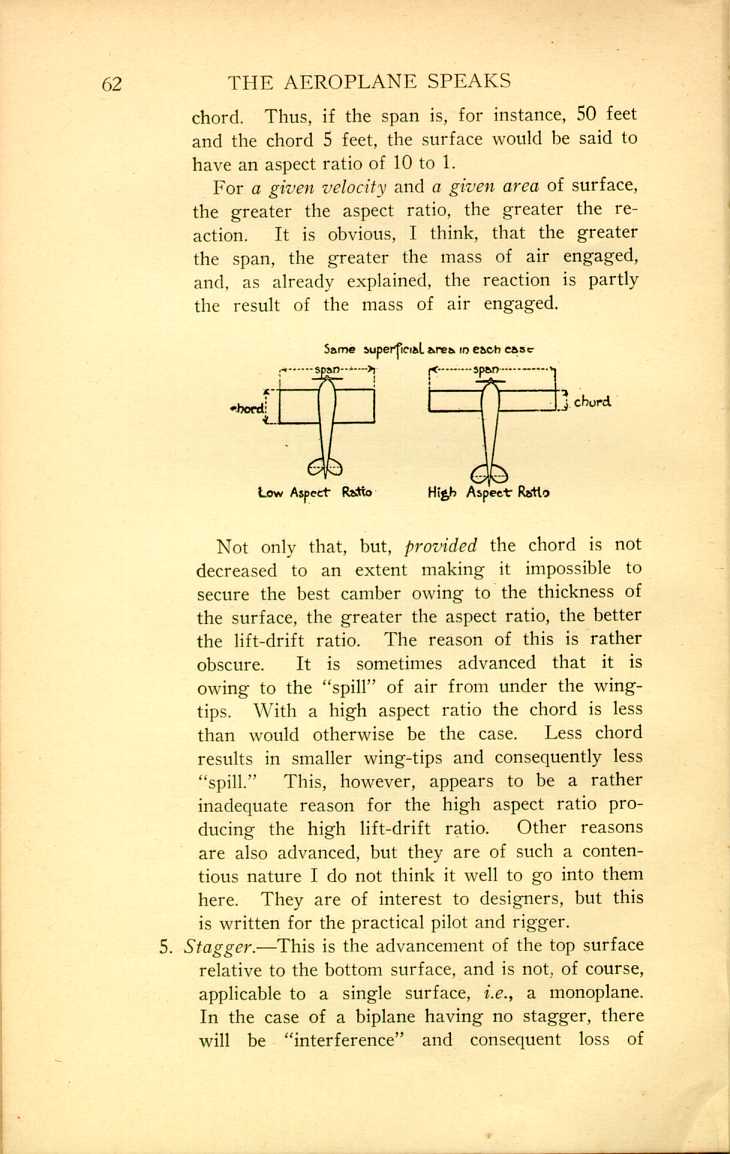
4. Aspect Ratio.—This is the proportion of span to
For a given velocity and a given area of surface, the greater the aspect ratio, the greater the reaction. It is obvious, I think, that the greater the span, the greater the mass of air engaged, and, as already explained, the reaction is partly the result of the mass of air engaged.
 [Description:
Diagram showing the effect of different aspect ratios.
]
[Description:
Diagram showing the effect of different aspect ratios.
]
Not only that, but, provided the chord is not decreased to an extent making it impossible to secure the best camber owing to the thickness of the surface, the greater the aspect ratio, the better the lift-drift ratio. The reason of this is rather obscure. It is sometimes advanced that it is owing to the "spill" of air from under the wing-tips. With a high aspect ratio the chord is less than would otherwise be the case. Less chord results in smaller wing-tips and consequently less "spill." This, however, appears to be a rather inadequate reason for the high aspect ratio producing the high lift-drift ratio. Other reasons are also advanced, but they are of such a contentious nature I do not think it well to go into them here. They are of interest to designers, but this is written for the practical pilot and rigger.
5. Stagger.—This is the advancement of the top surface relative to the bottom surface, and is not, of course, applicable to a single surface, i.e., a monoplane. In the case of a biplane having no stagger, there will be "interference" and consequent loss of
It is not practicable to have a gap of much
more than a distance equal to the chord, owing
to the drift produced by the great length of struts
and wires such a large gap would necessitate.
By staggering the top surface forward, however,
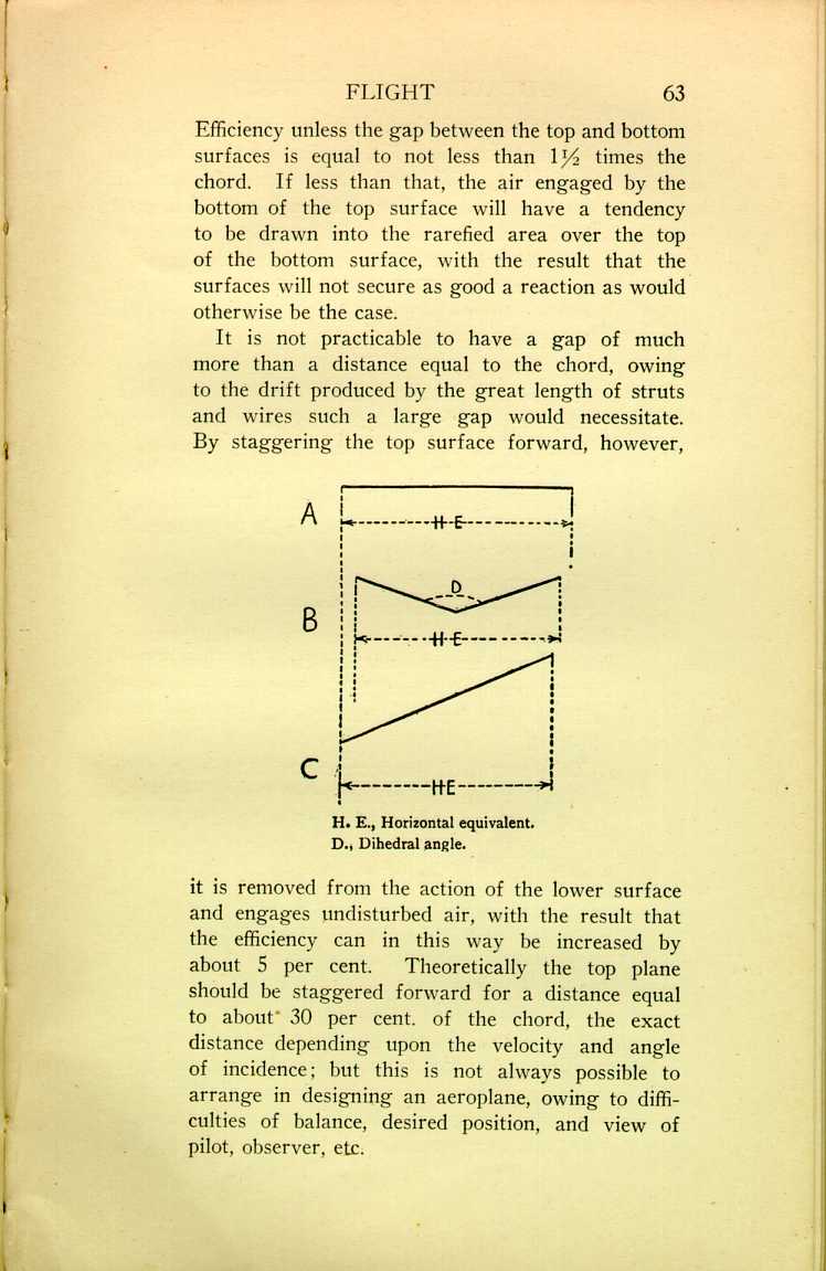
H.E., Horizontal equivalent.
[Description:
Diagram showing different surface angles.
]
D., Dihedral angle.
6. Horizontal Equivalent.—The vertical component of the reaction, i.e., lift, varies as the horizontal equivalent (H.E.) of the surface, but the drift remains the same. Then it follows that if H.E. grows less, the ratio of lift to drift must do the same.
A, B, and C are front views of three surfaces.
A has its full H.E., and therefore, from the point of view from which we are at the moment considering efficiency, it has its best lift-drift ratio.
B and C both possess the same surface as A, but one is inclined upwards from its centre and the other is straight but tilted. For these reasons their H.E.'s are, as illustrated, less than in the case of A. That means less vertical lift, and, the drift remaining the same (for there is the same amount of surface as in A to produce it), the lift-drift ratio falls.
The Margin of Power is the power available above that necessary to maintain horizontal flight.
The Margin of Lift is the height an aeroplane can gain in a given time and starting from a given altitude. As an example, thus: 1,000 feet the first minute, and starting from an altitude of 500 feet above sea-level.
The margin of lift decreases with altitude, owing to the decrease in the density of the air, which adversely affects the engine. Provided the engine maintained its impulse with altitude, then, if we ignore the problem of the propeller, which I will go into later on, the margin of lift would not disappear. Moreover, greater velocity for a given power would be secured at a greater altitude, owing to the decreased density of air to be overcome. After reading that, you may like to light your pipe and indulge in dreams of the wonderful possibilities which may become realities if some brilliant genius shows us some day how to secure a constant power with increasing altitude. I am afraid, however, that will always remain impossible; but it is probable
The Minimum Angle of Incidence is the smallest angle at which, for a given power, surface (including detrimental surface), and weight, horizontal flight can be maintained.
The Maximum Angle of Incidence is the greatest angle at which, for a given power, surface (including detrimental surface), and weight, horizontal flight can be maintained.
The Optimum Angle of Incidence is the angle at which the lift-drift ratio is highest. In modern aeroplanes it is that angle of incidence possessed by the surface when the axis of the propeller is horizontal.
The Best Climbing Angle is approximately half-way between the maximum and the optimum angles.
All present-day aeroplanes are a compromise between Climb and horizontal Velocity. We will compare the essentials for two aeroplanes, one designed for maximum climb, and the other for maximum velocity.
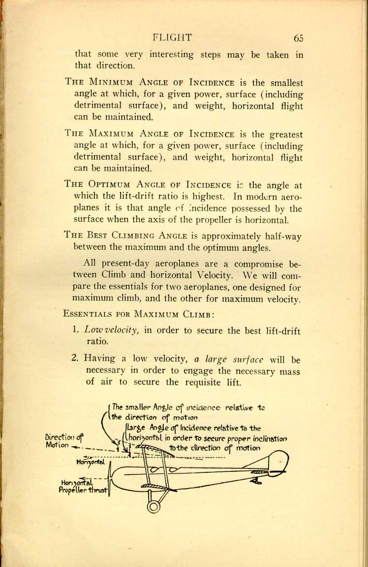
Essentials for Maximum Climb:
1. Low velocity, in order to secure the best lift-drift ratio.
2. Having a low velocity, a large surface will be necessary in order to engage the necessary mass of air to secure the requisite lift.
 [Description:
Diagram of a plane, demonstrating the angles of incidence.
]
[Description:
Diagram of a plane, demonstrating the angles of incidence.
]
3. Since (1) such a climbing machine will move along an upward sloping path, and (2) will climb with its propeller thrust horizontal, then a large angle relative to the direction of the thrust will be necessary in order to secure the requisite angle relative to the direction of motion.
The propeller thrust should be always horizontal, because the most efficient flying-machine (having regard to climb or velocity) has, so far, been found to be an arrangement of an inclined surface driven by a horizontal thrust—the surface lifting the weight, and the thrust overcoming the drift. This is, in practice, a far more efficient arrangement than the helicopter, i.e., the air-screw revolving about a vertical axis and producing a thrust opposed to gravity. If, when climbing, the propeller thrust is at such an angle as to tend to haul the aeroplane upwards, then it is, in a measure, acting as a helicopter, and that means inefficiency. The reason of a helicopter being inefficient in practice is due to the fact that, owing to mechanical difficulties, it is impossible to construct within a reasonable weight an air-screw of the requisite dimensions. That being so, it would be necessary, in order to absorb the power of the engine, to revolve the comparatively small-surfaced air screw at an immensely greater velocity than that of the aeroplane's surface. As already explained, the lift-drift ratio falls with velocity on account of the increase in passive drift. This applies to a blade of a propeller or air-screw, which is nothing but a revolving surface set at angle of incidence, and which it is impossible to construct without a good deal of detrimental surface near the central boss.
4. The velocity being low, then it follows that for that reason also the angle of incidence should be comparatively large.
5. Camber.—Since such an aeroplane would be of low velocity, and therefore possess a large angle of incidence, a large camber would be necessary.
Let us now consider the essentials for an aeroplane of maximum velocity for its power, and possessing merely enough lift to get off the ground, but no margin of lift.
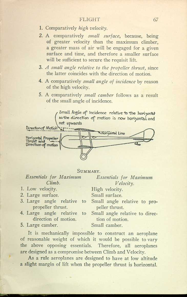
1. Comparatively high velocity.
2. A comparatively small surface, because, being of greater velocity than the maximum climber, a greater mass of air will be engaged for a given surface and time, and therefore a smaller surface will be sufficient to secure the requisit lift.
3. A small angle relative to the propeller thrust, since the latter coincides with the direction of motion.
4. A comparatively small angle of incidence by reason of the high velocity.
5. A comparatively small camber follows as a result of the small angle of incidence.
 [Description:
Diagram of a plane, demonstrating the angle of incidence.
]
[Description:
Diagram of a plane, demonstrating the angle of incidence.
]
| Essentials for Maximum Climb. | Essentials for Maximum Velocity |
| 1. Low velocity. | High velocity. |
| 2. Large surface. | Small surface. |
| 3. Large angle relative to propeller thrust. | Small angle relative to propeller thrust. |
| 4. Large angle relative to direction of motion. | Small angle relative to direction of motion. |
| 5. Large camber. | Small camber. |
It is mechanically impossible to construct an aeroplane of reasonable weight of which it would be possible to very the above opposing essentials. Therefore, all aeroplanes are designed as a compromise between Climb and Velocity.
As a rule aeroplanes are designed to have at low altitude a slight margin of lift when the propeller thrust is horizontal.
[3] Click here to see the text of the following figure in tabular format.
By this means, when the altitude is reached where the margin of lift disappears (on account of loss of engine power), and which is, consequently, the altitude where it is just possible to maintain horizontal flight, the aeroplane is flying with its thrust horizontal and with maximum efficiency (as distinct from engine and propeller efficiency).
The margin of lift at low altitude, and when the thrust is horizontal, should then be such that the higher altitude at which the margin of lift is lost is that altitude at which most of the aeroplane's horizontal flight work is done. That ensures maximum velocity when most required.
Unfortunately, where aeroplanes designed for fighting are concerned, the altitude where most of the work is done is that at which both maximum velocity and maximum margin of lift for power are required.
Perhaps some day a brilliant inventor will design an aeroplane of reasonable weight and drift of which it will be possible for the pilot to vary at will the above-mentioned opposing essentials. Then we shall get maximum velocity, or maximum margin of lift, for power as required. Until then the design of the aeroplane must remain a compromise between Velocity and Climb.
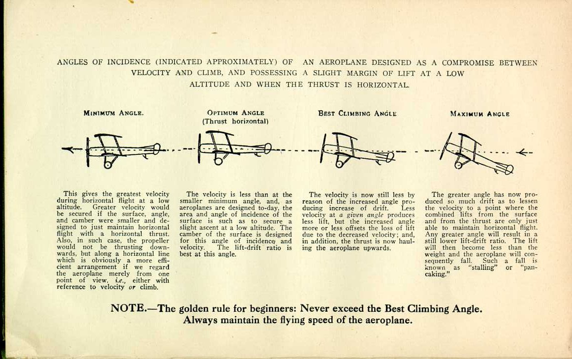
| MINIMUM ANGLE. | OPTIMUM ANGLE (Thrust horizontal) | BEST CLIMBING ANGLE | MAXIMUM ANGLE |
| This gives the greatest velocity during horizontal flight at a low altitude. Greater velocity would be secured if the surface, angle, and camber were smaller and designed to just maintain horizontal flight with a horizontal thrust . Also, in such case, the propeller would not be thrusting downwards, but along a horizontal line which is obviously a more efficient arrangement if we regard the aeroplane merely from one point of view, i.e., either with reference to velocity or climb. | |||
| The velocity is less than at the smaller minimum angle, and, as aeroplanes are designed to-day, the area and angle of incidence of the surface is such as to secure a slight ascent at a low altitude. The camber of the surface is designed for this angle of incidence and velocity. The lift-drift ratio is best at this angle. | |||
| The velocity is now still less by reason of the increased angle producing increase of drift. Less velocity at a given angle produces less lift, but the increased angle more or less offsets the loss of lift due to the decreased velocity, and, in addition, the thrust is now hauling the aeroplane upwards. | |||
| The greater angle has now produced so much drift as to lessen the velocity to a point where the combined lifts from the surface and from the thrust are only just able to maintain horizontal flight. Any greater angle will result in a still lower lift-drift ratio. The lift will then become less than the weight and the aeroplane will consequently fall. Such a fall is known as "stalling" or "pancaking." |
NOTE.—The golden rule for beginners: Never exceed the Best Climbing Angle. Always maintain the flying speed of the aeroplane.
|
CHAPTER I
FLIGHT
The Aeroplane Speaks | ||