|
CHAPTER III
RIGGING
The Aeroplane Speaks | ||
3.
CHAPTER III
RIGGING
In order to rig an aeroplane intelligently, and to maintain it in an efficient and safe condition, it is necessary to possess a knowledge of the stresses it is called upon to endure, and the strains likely to appear.
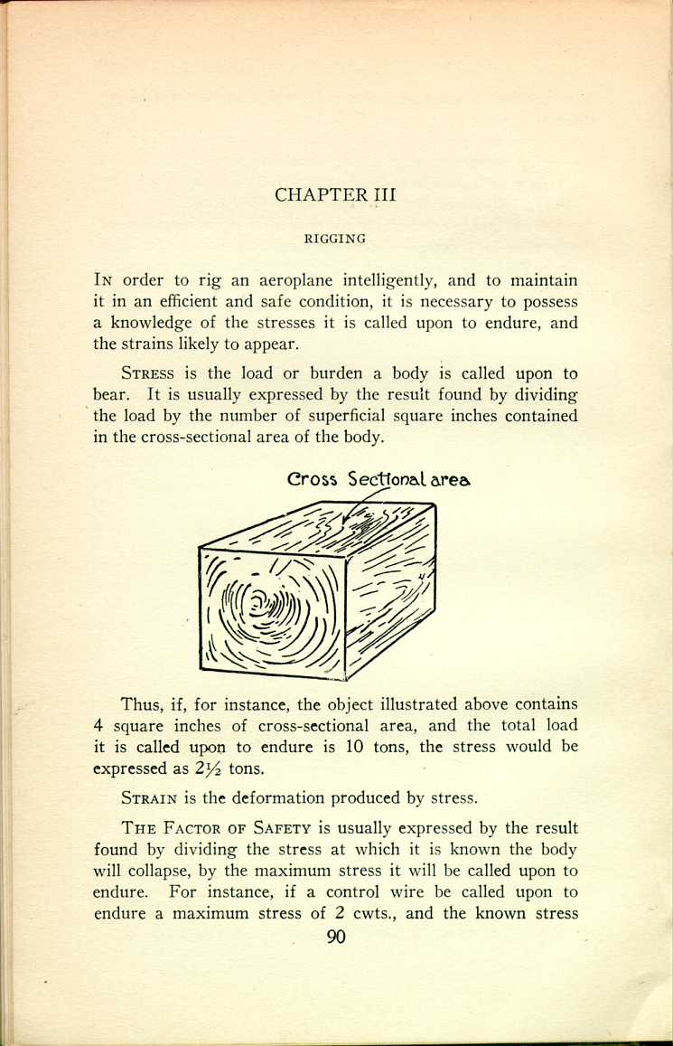
Stress is the load or burden a body is called upon to bear. It is usually expressed by the result found by dividing the load by the number of superficial square inches contained in the cross-sectional area of the body.
 [Description:
Diagram illustrating cross sectional area.
]
[Description:
Diagram illustrating cross sectional area.
]
Thus, if, for instance, the object illustrated above contains 4 square inches of cross-sectional area, and the total load it is called upon to endure is 10 tons, the stress would be expressed as 2 ½ tons.
Strain is the deformation produced by stress.
The Factor of Safety is usually expressed by the result found by dividing the stress at which it is known the body will collapse, by the maximum stress it will be called upon to endure. For instance, if a control wire be called upon to endure a maximum stress of 2 cwts., and the known stress
Compression.—The simple stress of compression tends to produce a crushing strain. Example: the interplane and fuselage struts.
Tension.—The simple stress of tension tends to produce the strain of elongation. Example: all the wires.
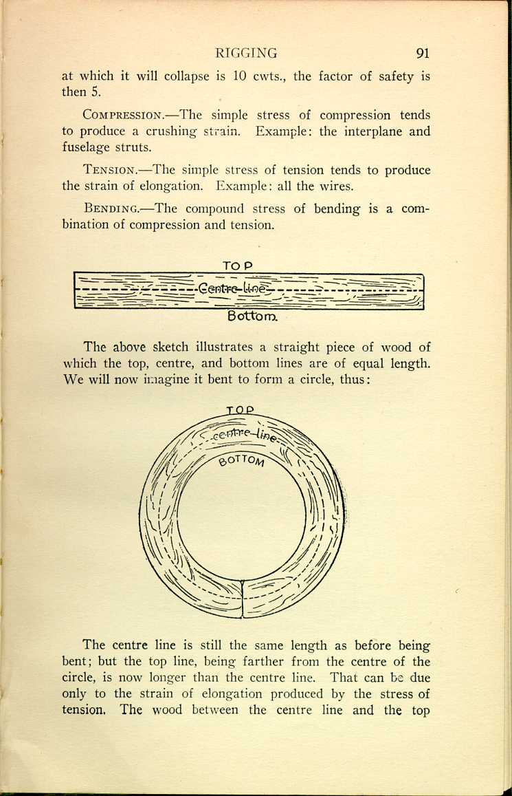
Bending.—The compound stress of bending is a combination of compression and tension.
 [Description:
Diagram of a piece of wood with top, central, and bottom lines labeled.
]
[Description:
Diagram of a piece of wood with top, central, and bottom lines labeled.
]
The above sketch illustrates a straight piece of wood of which the top, centre, and bottom lines are of equal length. We will now imagine it bent to form a circle, thus:

The centre line is still the same length as before being bent; but the top line, being farther from the centre of the circle, is now longer than the centre line. That can be due only to the strain of elongation produced by the stress of tension. The wood between the centre line and the top
The bottom line, being nearest to the centre of the circle, is now shorter than the centre line. That can be due only to the strain of crushing produced by the stress of compression. The wood between the centre and bottom lines is then in compression; and the nearer the centre of the circle, the greater the strain, and consequently the greater the compression.
It then follows that there is neither tension nor compression, i.e., no stress, at the centre line, and that the wood immediately surrounding it is under considerably less stress than the wood farther away. This being so, the wood in the centre may be hollowed out without unduly weakening struts and spars. In this way 25 to 33 per cent. is saved in the weight of wood in an aeroplane.
The strength of wood is in its fibres, which should, as far as possible, run without break from one end of a strut or spar to the other end. A point to remember is that the outside fibres, being farthest removed from the centre line, are doing by far the greatest work.
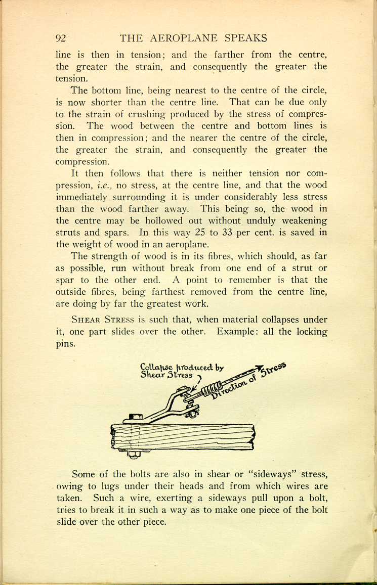
Shear Stress is such that, when material collapses under it, one part slides over the other. Example: all the locking pins.
 [Description:
Diagram demonstrating shear stress.
]
[Description:
Diagram demonstrating shear stress.
]
Some of the bolts are also in shear or "sideways" stress, owing to lugs under their heads and from which wires are taken. Such a wire, exerting a sideways pull upon a bolt, tries to break it in such a way as to make one piece of the bolt slide over the other piece.
Torsion.—This is a twisting stress compounded of compression, tension, and shear stresses. Example: the propeller shaft.
Nature of Wood Under Stress.—Wood, for its weight, takes the stress of compression far better than any other stress. For instance: a walking-stick of less than 1 lb. in weight will, if kept perfectly straight, probably stand up to a compression stress of a ton or more before crushing; whereas, if the same stick is put under a bending stress, it will probably collapse to a stress of not more than about 50 lb. That is a very great difference, and, since weight is of the greatest importance, the design of an aeroplane is always such as to, as far as possible, keep the various wooden parts of its construction in direct compression. Weight being of such vital importance, and designers all trying to outdo each other in saving weight, it follows that the factor of safety is rather low in an aeroplane. The parts in direct compression will, however, take the stresses safely provided the following conditions are carefully observed.
Conditions to be Observed:
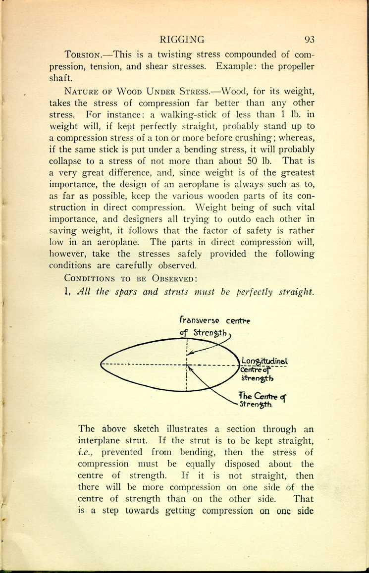
1. All the spars and struts must be perfectly straight.
 [Description:
Diagram of a strut with the centers of strength labeled.
]
[Description:
Diagram of a strut with the centers of strength labeled.
]
 [Description:
Illustration showing straight and bent struts.
]
[Description:
Illustration showing straight and bent struts.
]
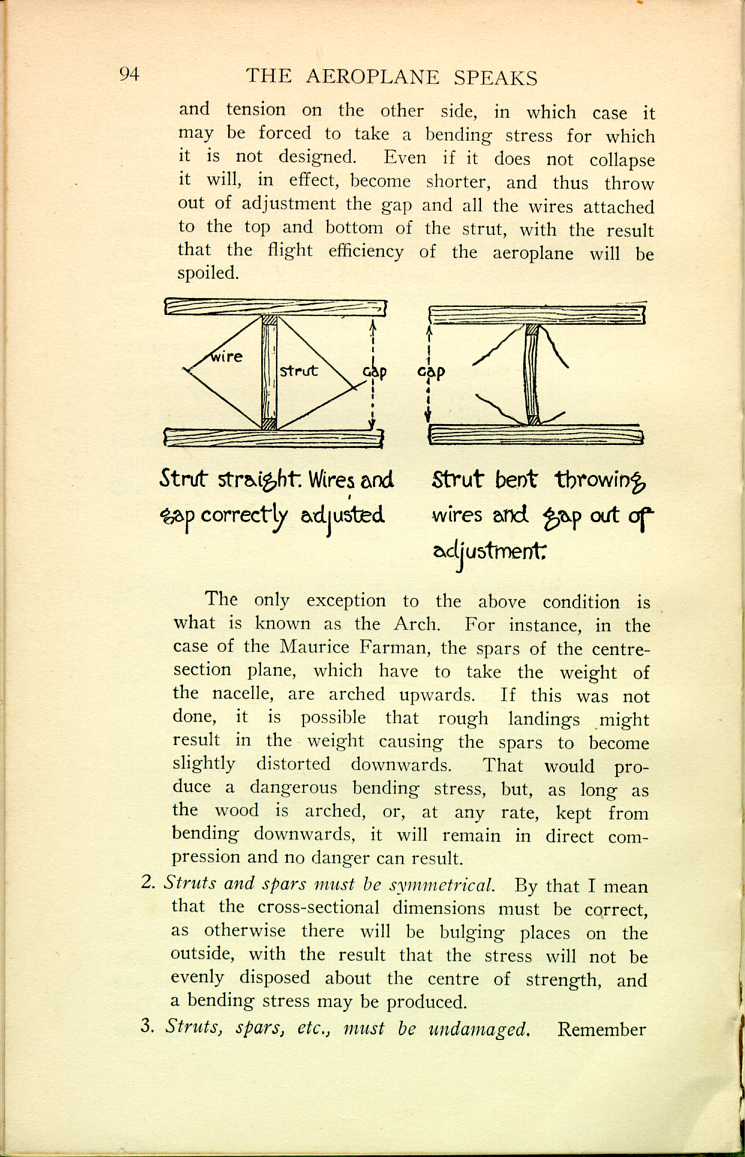
The only exception to the above condition is what is known as the Arch. For instance, in the case of the Maurice Farman, the spars of the centre-section plane, which have to take the weight of the nacelle, are arched upwards. If this was not done, it is possible that rough landings might result in the weight causing the spars to become slightly distorted downwards. That would produce a dangerous bending stress, but, as long as the wood is arched, or, at any rate, kept from bending downwards, it will remain in direct compression and no danger can result.
2. Struts and spars must be symmetrical. By that I mean that the cross-sectional dimensions must be correct, as otherwise there will be bulging places on the outside, with the result that the stress will not be evenly disposed about the centre of strength, and a bending stress may be produced.
3. Struts, spars, etc., must be undamaged. Remember
4. The wood must have a good, clear grain with no cross-grain, knots, or shakes. Such blemishes produce weak places and, if a tendency to bend appears, then it may collapse at such a point.
 [Description:
Illustration comparing proper and improper bedding of struts.
]
[Description:
Illustration comparing proper and improper bedding of struts.
]
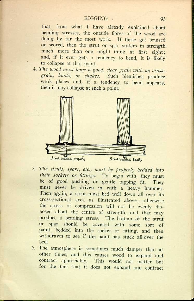
5. The struts, spars, etc., must be properly bedded into their sockets or fittings. To begin with, they must be of good pushing or gentle tapping fit. They must never be driven in with a heavy hammer. Then again, a strut must bed well down all over its cross-sectional area as illustrated above; otherwise the stress of compression will not be evenly disposed about the centre of strength, and that may produce a bending stress. The bottom of the strut or spar should be covered with some sort of paint, bedded into the socket or fitting, and then withdrawn to see if the paint has stuck all over the bed.
6. The atmosphere is sometimes much damper than at other times, and this causes wood to expand and contract appreciably. This would not matter but for the fact that it does not expand and contract
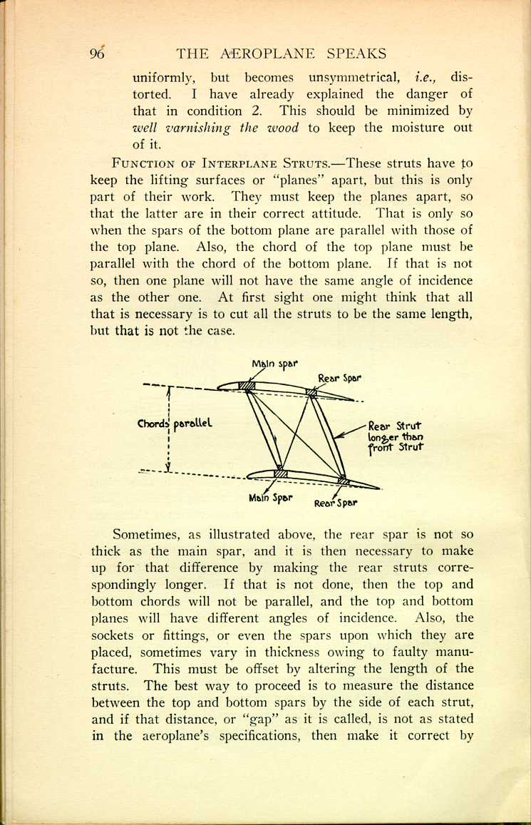
Function of Interplane Struts.—These struts have to keep the lifting surfaces or "planes" apart, but this is only part of their work. They must keep the planes apart, so that the latter are in their correct attitude. That is only so when the spars of the bottom plane are parallel with those of the top plane. Also, the chord of the top plane must be parallel with the chord of the bottom plane. If that is not so, then one plane will not have the same angle of incidence as the other one. At first sight one might think that all that is necessary is to cut all the struts to be the same length, but that is not the case.
 [Description:
Diagram showing the position of interplane struts.
]
[Description:
Diagram showing the position of interplane struts.
]
Sometimes, as illustrated above, the rear spar is not so thick as the main spar, and it is then necessary to make up for that difference by making the rear struts correspondingly longer. If that is not done, then the top and bottom chords will not be parallel, and the top and bottom planes will have different angles of incidence. Also, the sockets or fittings, or even the spars upon which they are placed, sometimes vary in thickness owing to faulty manufacture. This must be offset by altering the length of the struts. The best way to proceed is to measure the distance between the top and bottom spars by the side of each strut, and if that distance, or "gap" as it is called, is not as stated in the aeroplane's specifications, then make it correct by
Boring Holes in Wood.—It should be a strict rule that no spar be used which has an unnecessary hole in it. Before boring a hole, its position should be confirmed by whoever is in charge of the workshop. A bolt-hole should be of a size to enable the bolt to be pushed in, or, at any rate, not more than gently tapped in. Bolts should not be hammered in, as that may split the spar. On the other hand, a bolt should not be slack in its hole, as, in such a case, it may work sideways and split the spar, not to speak of throwing out of adjustment the wires leading from the lug or socket under the bolt-head.
Washers.—Under the bolt-head, and also under the nut, a washer must be placed—a very large washer compared with the size which would be used in all-metal construction. This is to disperse the stress over a large area; otherwise the washer may be pulled into the wood and weaken it, besides possibly throwing out of adjustment the wires attached to the bolt or the fitting it is holding to the spar.
Locking.—Now as regards locking the bolts. If split pins are used, be sure to see that they are used in such a way that the nut cannot possibly unscrew at all. The split pin should be passed through the bolt as near as possible to the nut. It should not be passed through both nut and bolt.
If it is locked by burring over the edge of the bolt, do not use a heavy hammer and try to spread the whole head of the bolt. That might damage the woodwork inside the fabric-covered surface. Use a small, light hammer, and gently tap round the edge of the bolt until it is burred over.
Turnbuckles.—A turnbuckle is composed of a central barrel into each end of which is screwed an eye-bolt. Wires are taken from the eyes of the eye-bolt, and so, by turning the barrel, they can be adjusted to their proper tension. Eye-bolts must be a good fit in the barrel; that is to say, not slack and not very tight. Theoretically it is not necessary
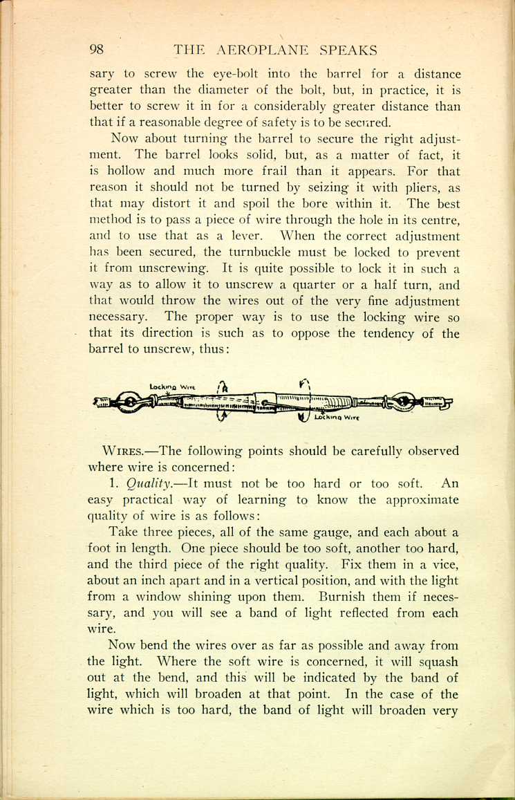
Now about turning the barrel to secure the right adjustment. The barrel looks solid, but, as a matter of fact, it is hollow and much more frail than it appears. For that reason it should not be turned by seizing it with pliers, as that may distort it and spoil the bore within it. The best method is to pass a piece of wire through the hole in its centre, and to use that as a lever. When the correct adjustment has been secured, the turnbuckle must be locked to prevent it from unscrewing. It is quite possible to lock it in such a way as to allow it to unscrew a quarter or a half turn, and that would throw the wires out of the very fine adjustment necessary. The proper way is to use the locking wire so that its direction is such as to oppose the tendency of the barrel to unscrew, thus:
 [Description:
Illustration showing a locking wire.
]
[Description:
Illustration showing a locking wire.
]
Wires.—The following points should be carefully observed where wire is concerned:
1. Quality.—It must not be too hard or too soft. An easy practical way of learning to know the approximate quality of wire is as follows:
Take three pieces, all of the same gauge, and each about a foot in length. One piece should be too soft, another too hard, and the third piece of the right quality. Fix them in a vice, about an inch apart and in a vertical position, and with the light from a window shining upon them. Burnish them if necessary, and you will see a band of light reflected from each wire.
Now bend the wires over as far as possible and away from the light. Where the soft wire is concerned, it will squash out at the bend, and this will be indicated by the band of light, which will broaden at that point. In the case of the wire which is too hard, the band of light will broaden very
By making this experiment two or three times one can soon learn to know really bad wire from good, and also learn to know the strength of hand necessary to bend the right quality.
2. It must not be damaged. That is to say, it must be unkinked, rustless, and unscored.
3. Now as regards keeping wire in good condition. Where outside wires are concerned, they should be kept well greased or oiled, especially where bent over at the ends. Internal bracing wires cannot be reached for the purpose of regreasing them, as they are inside fabric-covered surfaces. They should be prevented from rusting by being painted with an anti-rust mixture. Great care should be taken to see that the wire is perfectly clean and dry before being painted. A greasy finger-mark is sufficient to stop the paint from sticking to the wire. In such a case there will be a little space between the paint and the wire. Air may enter there and cause the wire to rust.
4. Tension of Wires.—The tension to which the wires are adjusted is of the greatest importance. All the wires should be of the same tension when the aeroplane is supported in such a way as to throw no stress upon them. If some wires are in greater tension than others, the aeroplane will quickly become distorted and lose its efficiency.
In order to secure the same tension of all wires, the aeroplane, when being rigged, should be supported by packing underneath the lower surfaces as well as by packing underneath the fuselage or nacelle. In this way the anti-lift wires are relieved of the weight, and there is no stress upon any of the wires.
As a general rule the wires of an aeroplane are tensioned too much. The tension should be sufficient to keep the framework rigid. Anything more than that lowers the factor of safety, throws various parts of the framework into undue compression, pulls the fittings into the wood, and will, in the end, distort the whole framework of the aeroplane.
Only experience will teach the rigger what tension to employ. Much may be done by learning the construction of the various types of aeroplanes, the work the various parts do, and in cultivating a touch for tensioning wires by constantly handling them.
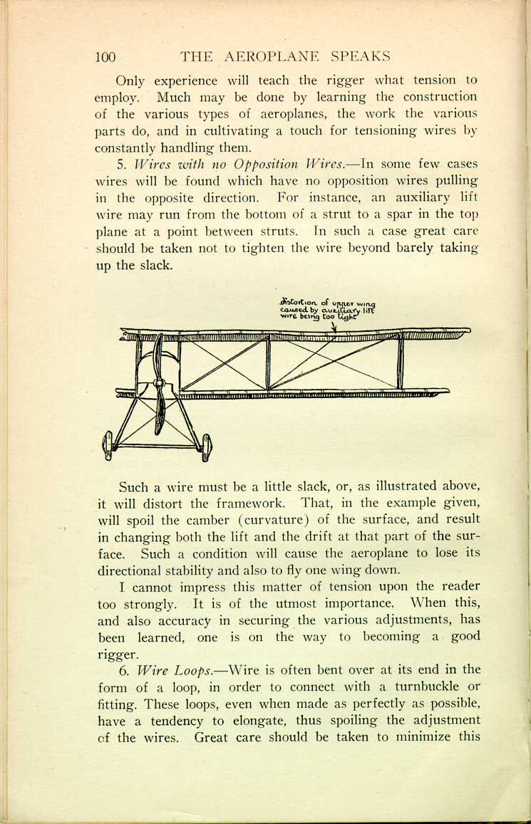
5. Wires with no Opposition Wires.—In some few cases wires will be found which have no opposition wires pulling in the opposite direction. For instance, an auxiliary lift wire may run from the bottom of a strut to a spar in the top plane at a point between struts. In such a case great care should be taken not to tighten the wire beyond barely taking up the slack.
 [Description:
Illustration of a biplane wing, showing the arrangement of wires.
]
[Description:
Illustration of a biplane wing, showing the arrangement of wires.
]
Such a wire must be a little slack, or, as illustrated above, it will distort the framework. That, in the example given, will spoil the camber (curvature) of the surface, and result in changing both the lift and the drift at that part of the surface. Such a condition will cause the aeroplane to lose its directional stability and also to fly one wing down.
I cannot impress this matter of tension upon the reader too strongly. It is of the utmost importance. When this, and also accuracy in securing the various adjustments, has been learned, one is on the way to becoming a good rigger.
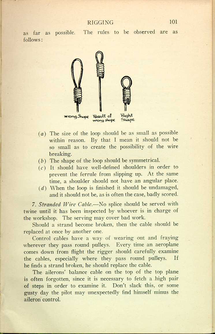
6. Wire Loops.—Wire is often bent over at its end in the form of a loop, in order to connect with a turnbuckle or fitting. These loops, even when made as perfectly as possible, have a tendency to elongate, thus spoiling the adjustment of the wires Great care should be taken to minimize this
 [Description:
Illustration comparing correctly and incorrectly formed wire loops.
]
[Description:
Illustration comparing correctly and incorrectly formed wire loops.
]
(a) The size of the loop should be as small as possible within reason. By that I mean it should not be so small as to create the possibility of the wire breaking.
(b) The shape of the loop should be symmetrical.
(c) It should have well-defined shoulders in order to prevent the ferrule from slipping up. At the same time, a shoulder should not have an angular place.
(d) When the loop is finished it should be undamaged, and it should not be, as is often the case, badly scored.
7. Stranded Wire Cable.—No splice should be served with twine until it has been inspected by whoever is in charge of the workshop. The serving may cover bad work.
Should a strand become broken, then the cable should be replaced at once by another one.
Control cables have a way of wearing out and fraying wherever they pass round pulleys. Every time an aeroplane comes down from flight the rigger should carefully examine the cables, especially where they pass round pulleys. If he finds a strand broken, he should replace the cable.
The ailerons' balance cable on the top of the top plane is often forgotten, since it is necessary to fetch a high pair of steps in order to examine it. Don't slack this, or some gusty day the pilot may unexpectedly find himself minus the aileron control.
Controlling Surfaces.—The greatest care should be exercised in rigging the aileron, rudder, and elevator properly, for the pilot entirely depends upon them in managing the aeroplane.
 [Description:
Diagram of a non-lifting surface.
]
[Description:
Diagram of a non-lifting surface.
]
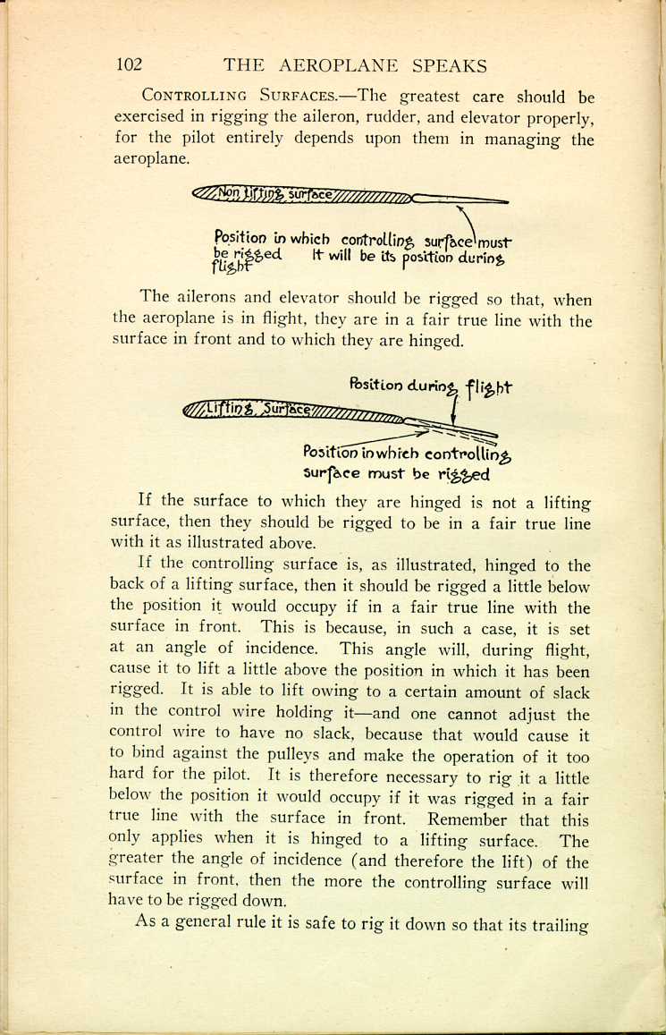
The ailerons and elevator should be rigged so that, when the aeroplane is in flight, they are in a fair true line with the surface in front and to which they are hinged.
 [Description:
Diagram of a lifting surface.
]
[Description:
Diagram of a lifting surface.
]
If the surface to which they are hinged is not a lifting surface, then they should be rigged to be in a fair true line with it as illustrated above.
If the controlling surface is, as illustrated, hinged to the back of a lifting surface, then it should be rigged a little below the position it would occupy if in a fair true line with the surface in front. This is because, in such a case, it is set at an angle of incidence. This angle will, during flight, cause it to lift a little above the position in which it has been rigged. It is able to lift owing to a certain amount of slack in the control wire holding it—and one cannot adjust the control wire to have no slack, because that would cause it to bind against the pulleys and make the operation of it too hard for the pilot. It is therefore necessary to rig it a little below the position it would occupy if it was rigged in a fair true line with the surface in front. Remember that this only applies when it is hinged to a lifting surface. The greater the angle of incidence (and therefore the lift) of the surface in front, then the more the controlling surface will have to be rigged down.
As a general rule it is safe to rig it down so that its trailing
When making these adjustments the pilot's control levers should be in their neutral positions. It is not sufficient to lash them. They should be rigidly blocked into position with wood packing.
The surfaces must not be distorted in any way. If they are held true by bracing wires, then such wires must be carefully adjusted. If they are distorted and there are no bracing wires with which to true them, then some of the internal framework will probably have to be replaced.
The controlling surfaces should never be adjusted with a view to altering the stability of the aeroplane. Nothing can be accomplished in that way. The only result will be to spoil the control of the aeroplane.
Fabric-Covered Surfaces.—First of all make sure that there is no distortion of spars or ribs, and that they are perfectly sound. Then adjust the internal bracing wires so that the ribs are parallel to the direction of flight. The ribs usually cause the fabric to make a ridge where they occur, and, if such ridge is not parallel to the direction of flight, it will produce excessive drift. As a rule the ribs are at right angles to both main and rear spars.
The tension of the internal bracing wires should be just sufficient to give rigidity to the framework. They should not be tensioned above that unless the wires are, at their ends, bent to form loops. In that case a little extra tension may be given to offset the probable elongation of the loops.
The turnbuckles must now be generously greased, and served round with adhesive tape. The wires must be rendered perfectly dry and clean, and then painted with an anti-rust mixture. The woodwork must be well varnished.
If it is necessary to bore holes in the spars for the purpose of receiving, for instance, socket bolts, then their places should be marked before being bored and their positions confirmed by whoever is in charge of the workshop. All is now ready for the sail-maker to cover the surface with fabric.
Adjustment of Control Cables.—The adjustment of the control cables is quite an art, and upon it will depend to a large degree the quick and easy control of the aeroplane by the pilot.
The method is as follows:
After having rigged the controlling surfaces, and as far as possible secured the correct adjustment of the control cables, then remove the packing which has kept the control levers rigid. Then, sitting in the pilot's seat, move the control levers smartly. Tension the control cables so that when the levers are smartly moved there is no perceptible snatch or lag. Be careful not to tension the cables more than necessary to take out the snatch. If tensioned too much they will (1) bind round the pulleys and result in hard work for the pilot; (2) throw dangerous stresses upon the controlling surfaces, which are of rather flimsy construction; and (3) cause the cables to fray round the pulleys quicker than would otherwise be the case.
Now, after having tensioned the cables sufficiently to take out the snatch, place the levers in their neutral positions, and move them to and fro about 1/8 inch either side of such positions. If the adjustment is correct, it should be possible to see the controlling surfaces move. If they do not move, then the control cables are too slack.
Flying Position.—Before rigging an aeroplane or making any adjustments it is necessary to place it in what is known as its "flying position." I may add that it would be better termed its "rigging position."
In the case of an aeroplane fitted with a stationary engine this is secured by packing up the machine so that the engine foundations are perfectly horizontal both longitudinally and laterally. This position is found by placing a straight-edge and a spirit-level across the engine foundations (both longitudinally and laterally), and great care should be taken to see that the bubble is exactly in the centre of the level. The slightest error will assume magnitude towards the extremities of the aeroplane. Great care should be taken to block up the aeroplane rigidly. In case it gets accidentally disturbed while the work is going on, it is well to constantly verify the flying position by running the straight-edge and spirit-level
In the case of aeroplanes fitted with engines of the rotary type, the "flying position" is some special attitude laid down in the aeroplane's specifications, and great care should be taken to secure accuracy.
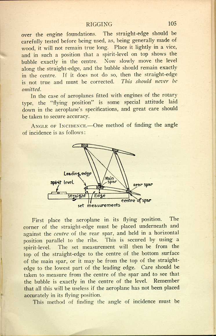
Angle of Incidence.—One method of finding the angle of incidence is as follows:
 [Description:
Diagram showing how to measure the angle of incidence.
]
[Description:
Diagram showing how to measure the angle of incidence.
]
First place the aeroplane in its flying position. The corner of the straight-edge must be placed underneath and against the centre of the rear spar, and held in a horizontal position parallel to the ribs. This is secured by using a spirit-level. The set measurement will then be from the top of the straight-edge to the centre of the bottom surface of the main spar, or it may be from the top of the straight-edge to the lowest part of the leading edge. Care should be taken to measure from the centre of the spar and to see that the bubble is exactly in the centre of the level. Remember that all this will be useless if the aeroplane has not been placed accurately in its flying position.
This method of finding the angle of incidence must be
If the angle is wrong, it should then be corrected as follows:
If it is too great, then the rear spar must be warped up until it is right, and this is done by slackening all the wires going to the top of the strut, and then tightening all the wires going to the bottom of the strut.
If the angle is too small, then slacken all the wires going to the bottom of the strut, and tighten all the wires going to the top of the strut, until the correct adjustment is secured.
Never attempt to adjust the angle by warping the main spar.
The set measurement, which is of course stated in the aeroplane's specifications, should be accurate to 1/16 inch.
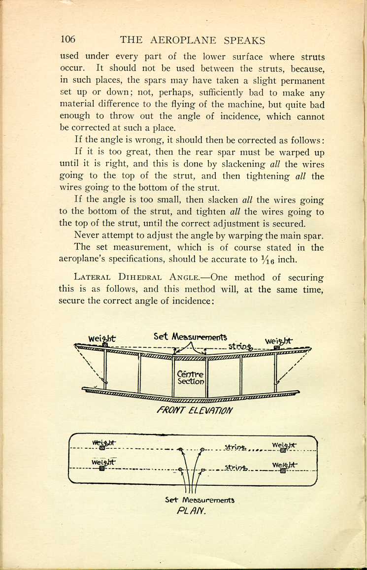
Lateral Dihedral Angle.—One method of securing this is as follows, and this method will, at the same time, secure the correct angle of incidence:
 [Description:
Diagram showing how to determine the proper measurements for the wings.
]
[Description:
Diagram showing how to determine the proper measurements for the wings.
]
The strings, drawn very tight, must be taken over both the main and rear spars of the top surface. They must run between points on the spars just inside the outer struts. The set measurement (which should be accurate to 1/16 inch or less) is then from the strings down to four points on the main and rear spars of the centre-section surface. These points should be just inside the four centre-section struts; that is to say, as far as possible away from the centre of the centre-section. Do not attempt to take the set measurement near the centre of the centre-section.
The strings should be as tight as possible, and, if it can be arranged, the best way to accomplish that is as shown in the above illustration, i.e., by weighting the strings down to the spars by means of weights and tying each end of the strings to a strut. This will give a tight and motionless string.
However carefully the above adjustment is made, there is sure to be some slight error. This is of no great importance, provided it is divided equally between the left-and right-hand wings. In order to make sure of this, certain check measurements should be taken as follows:
Each bay must be diagonally measured, and such measurements must be the same to within 1/16 inch on each side of the aeroplane. As a rule such diagonal measurements are taken from the bottom socket of one strut to the top socket of another strut, but this is bad practice, because of possible inaccuracies due to faulty manufacture.
The points between which the diagonal measurements are taken should be at fixed distances from the butts of the spars, such distances being the same on each side of the aeroplane, thus:
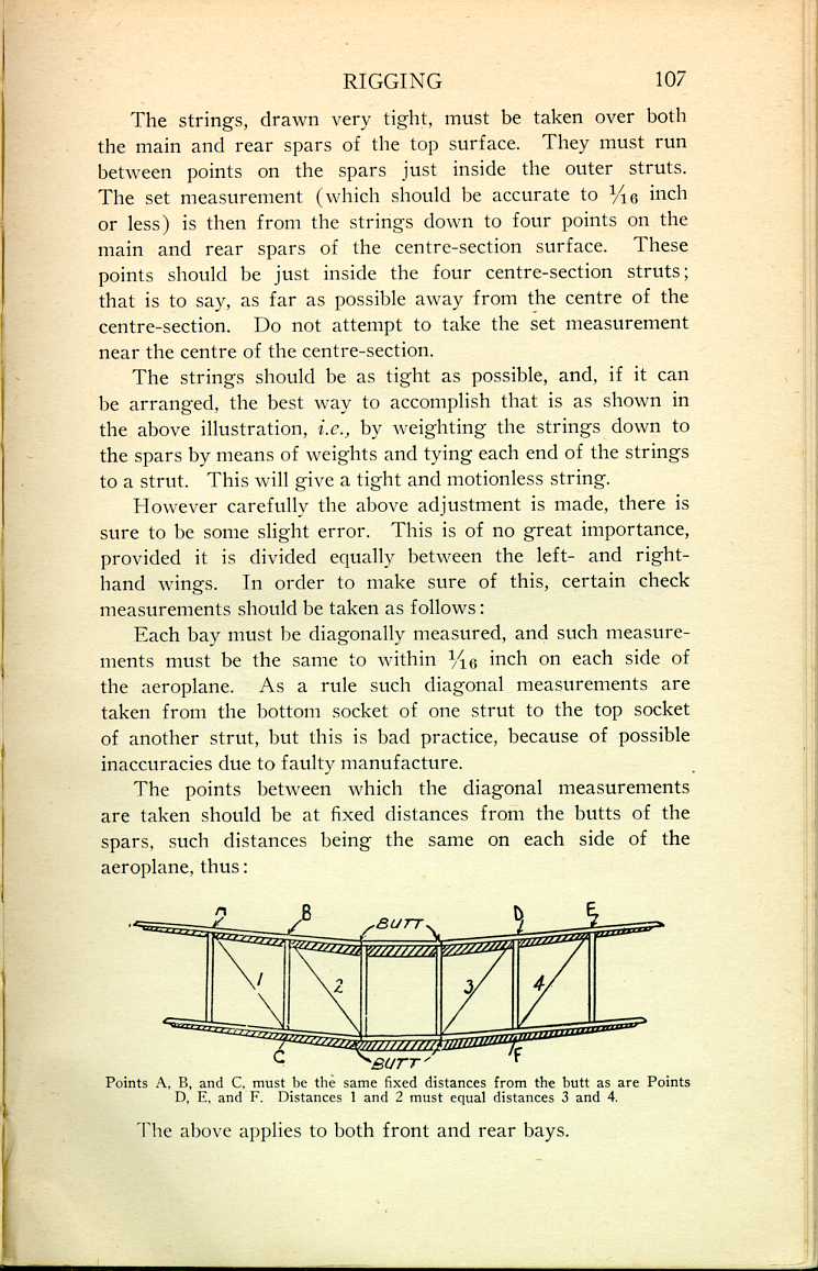
The above applies to both front and rear bays.
It would be better to use the centre line of the aeroplane rather than the butts of the spars. It is not practicable to do so, however, as the centre line probably runs through the petrol tanks, etc.
The Dihedral Board.—Another method of securing the dihedral angle, and also the angle of incidence, is by means of the dihedral board. It is a light handy thing to use, but leads to many errors, and should not be used unless necessary. The reasons are as follows:
The dihedral board is probably not true. If it must be used, then it should be very carefully tested for truth before-hand. Another reason against its use is that it has to be placed on the spars in a position between the struts, and that is just where the spars may have a little permanent set up or down, or some inaccuracy of surface which will, of course, throw out the accuracy of the adjustment. The method of using it is as follows:
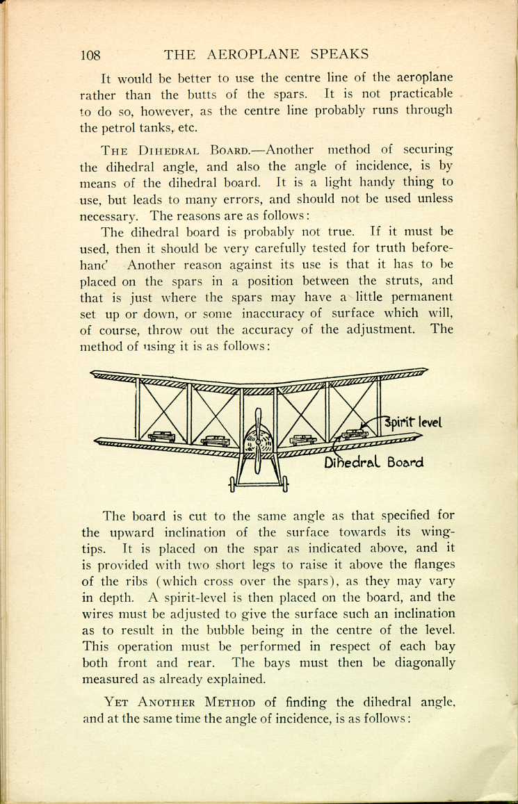
The board is cut to the same angle as that specified for the upward inclination of the surface towards its wing-tips. It is placed on the spar as indicated above, and it is provided with two short legs to raise it above the flanges of the ribs (which cross over the spars), as they may vary in depth. A spirit-level is then placed on the board, and the wires must be adjusted to give the surface such an inclination as to result in the bubble being in the centre of the level. This operation must be performed in respect of each bay both front and rear. The bays must then be diagonally measured as already explained.
Yet Another Method of finding the dihedral angle, and at the same time the angle of incidence, is as follows:
A horizontal line is taken from underneath the butt of each spar, and the set measurement is either the angle it makes with the spar, or a fixed measurement from the line to the spar taken at a specified distance from the butt. This operation must be performed in respect of both main and rear spars, and all the bays must be measured diagonally afterwards.

Whichever method is used, be sure that after the job is done the spars are perfectly straight.
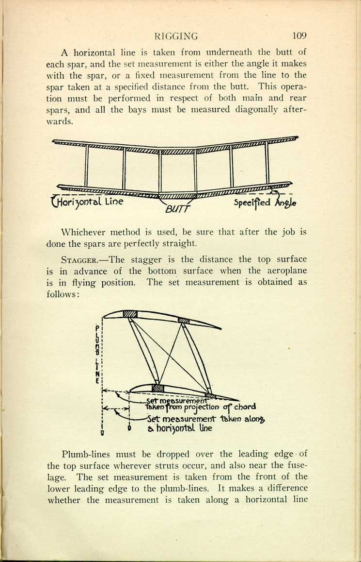
Stagger.—The stagger is the distance the top surface is in advance of the bottom surface when the aeroplane is in flying position. The set measurement is obtained as follows:
 [Description:
Diagram illustrating the stagger of a plane's surfaces.
]
[Description:
Diagram illustrating the stagger of a plane's surfaces.
]
Plumb-lines must be dropped over the leading edge of the top surface wherever struts occur, and also near the fuselage. The set measurement is taken from the front of the lower leading edge to the plumb-lines. It makes a difference whether the measurement is taken along a horizontal line
If a mistake is made and the measurement taken along the wrong line, it may result in a difference of perhaps ¼ inch or more to the stagger, with the certain result that the aeroplane will, in flight, be nose-heavy or tail-heavy.
After the adjustments of the angles of incidence, dihedral, and stagger have been secured, it is as well to confirm all of them, as, in making the last adjustment, the first one may have been spoiled.
Over-All Adjustments.—The following over-all check measurements should now be taken.
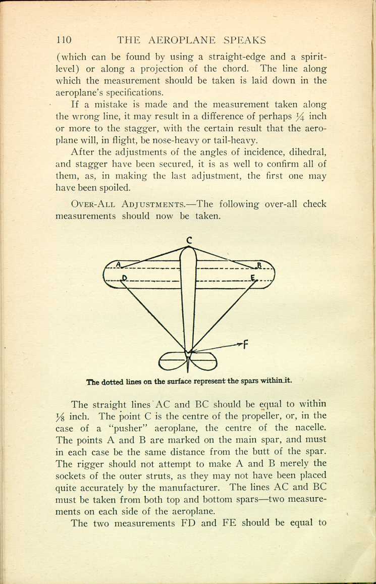
The straight lines AC and BC should be equal to within 1/8 inch. The point C is the centre of the propeller, or, in the case of a "pusher" aeroplane, the centre of the nacelle. The points A and B are marked on the main spar, and must in each case be the same distance from the butt of the spar. The rigger should not attempt to make A and B merely the sockets of the outer struts, as they may not have been placed quite accurately by the manufacturer. The lines AC and BC must be taken from both top and bottom spars—two measurements on each side of the aeroplane.
The two measurements FD and FE should be equal to
If these over-all measurements are not correct, then it is probably due to some of the drift or anti-drift wires being too tight or too slack. It may possibly be due to the fuselage being out of truth, but of course the rigger should have made quite sure that the fuselage was true before rigging the rest of the machine. Again, it may be due to the internal bracing wires within the lifting surfaces not being accurately adjusted, but of course this should have been seen to before covering the surfaces with fabric.
Fuselage.—The method of truing the fuselage is laid down in the aeroplane's specifications. After it has been adjusted according to the specified directions, it should then be arranged on trestles in such a way as to make about three-quarters of it towards the tail stick out unsupported. In this way it will assume a condition as near as possible to flying conditions, and when it is in this position the set measurements should be confirmed. If this is not done it may be out of truth, but perhaps appear all right when supported by trestles at both ends, as, in such case, its weight may keep it true as long as it is resting upon the trestles.
The Tail-Plane (Empennage).—The exact angle of incidence of the tail-plane is laid down in the aeroplane's specifications. It is necessary to make sure that the spars are horizontal when the aeroplane is in flying position and the tail unsupported as explained above under the heading of Fuselage. If the spars are tapered, then make sure that their centre lines are horizontal.
Undercarriage.—The undercarriage must be very carefully aligned as laid down in the specifications.
1. The aeroplane must be placed in its flying position and sufficiently high to ensure the wheels being off the ground when rigged. When in this position the axle must be horizontal
2. Make sure that the struts bed well down into their sockets.
3. Make sure that the shock absorbers are of equal tension. In the case of rubber shock absorbers, both the number of turns and the lengths must be equal.
How to Diagnose Faults in Flight, Stability, and Control..
Directional Stability will be badly affected if there is more drift (i.e., resistance) on one side of the aeroplane than there is on the other side. The aeroplane will tend to turn towards the side having the most drift. This may be caused as follows:
1. The angle of incidence of the main surface or the tail surface may be wrong. The greater the angle of incidence, the greater the drift. The less the angle, the less the drift.
2. If the alignment of the fuselage, fin in front of the rudder, the struts or stream-line wires, or, in the case of the Maurice Farman, the front outriggers, are not absolutely correct—that is to say, if they are turned a little to the left or to the right instead of being in line with the direction of flight—then they will act as a rudder and cause the aeroplane to turn off its course.
3. If any part of the surface is distorted, it will cause the aeroplane to turn off its course. The surface is cambered, i.e., curved, to pass through the air with the least possible drift. If, owing perhaps to the leading edge, spars, or trailing edge becoming bent, the curvature is spoiled, that will result in changing the amount of drift on one side of the aeroplane, which will then have a tendency to turn off its course.
Lateral Instability (Flying One Wing Down).—The only possible reason for such a condition is a difference in the lifts of right and left wings. That may be caused as follows:
1. The angle of incidence may be wrong. If it is too great, it will produce more lift than on the other side of the aeroplane; and if too small, it will produce less lift than on
2. Distorted Surfaces.—If some part of the surface is distorted, then its camber is spoiled, and the lift will not be the same on both sides of the aeroplane, and that, of course, will cause it to fly one wing down.
Longitudinal Instability may be due to the following reasons:
1. The stagger may be wrong. The top surface may have drifted back a little owing to some of the wires, probably the incidence wires, having elongated their loops or having pulled the fittings into the wood. If the top surface is not staggered forward to the correct degree, then consequently the whole of its lift is too far back, and it will then have a tendency to lift up the tail of the machine too much. The aeroplane would then be said to be "nose-heavy."
A ¼-inch area in the stagger will make a very considerable difference to the longitudinal stability.
2. If the angle of incidence of the main surface is not right, it will have a bad effect, especially in the case of an aeroplane with a lifting tail-plane.
If the angle is too great, it will produce an excess of lift, and that may lift up the nose of the aeroplane and result in a tendency to fly "tail-down." If the angle is too small, it will produce a decreased lift, and the aeroplane may have a tendency to fly "nose-down."
3. The fuselage may have become warped upward or downward, thus giving the tail-plane an incorrect angle of incidence. If it has too much angle, it will lift too much, and the aeroplane will be "nose-heavy." If it has too little angle, then it will not lift enough, and the aeroplane will be "tail-heavy."
4. (The least likely reason.) The tail-plane may be mounted upon the fuselage at a wrong angle of incidence, in which case it must be corrected. If nose-heavy, it should be given a smaller angle of incidence. If tail-heavy, it should be given a larger angle; but care should be taken not to give it too great an angle, because the longitudinal stability entirely depends upon the tail-plane being set at a much
Climbs Badly.—Such a condition is, apart from engine or propeller trouble, probably due to (1) distorted surfaces, or (2) too small an angle of incidence.
Flight Speed Poor.—Such a condition is, apart from engine or propeller trouble, probably due to (1) distorted surfaces, (2) too great an angle of incidence, or (3) dirt or mud, and consequently excessive skin-friction.
Inefficient Control is probably due to (1) wrong setting of control surfaces, (2) distortion of control surfaces, or (3) control cables being badly tensioned.
Will not "Taxi" Straight.—If the aeroplane is uncontrollable on the ground, it is probably due to (1) alignment of undercarriage being wrong, or (2) unequal tension of shock absorbers.
|
CHAPTER III
RIGGING
The Aeroplane Speaks | ||