| CHAPTER XIV
EXPERIMENTAL GLIDERS AND MODEL AEROPLANES Aeroplanes | ||
14. CHAPTER XIV
EXPERIMENTAL GLIDERS AND MODEL AEROPLANES
AN amusing and very instructive pastime is afforded by constructing and flying gliding machines, and operating model aeroplanes, the latter being equipped with their own power.
Abroad this work has been very successful as a means of interesting boys, and, indeed, men who have taken up the science of aviation are giving this sport serious thought and study.
When a machine of small dimensions is made the boy wonders why a large machine does not bear the same relation in weight as a small machine. This is one of the first lessons to learn.
THE RELATION OF MODELS TO FLYING MACHINES.—A model aeroplane, say two feet in length, which has, we will assume, 50 square inches of supporting surface, seems to be a very rigid structure, in proportion to its weight. It may be dropped from a considerable height without injuring it, since the weight is only between two and three ounces.
An aeroplane twenty times the length of this
If the large machine is twenty times the dimensions of the small one, it would be forty feet in length, and, proportionally, would have only seven square feet of sustaining surface. But an operative machine of that size, to be at all rigid, would require more than twenty times the material in weight to be equal in strength.
It would weigh about 800 pounds, that is, 4800 times the weight of the model, and instead of having twenty times the plane surface would require one thousand times the spread.
It is this peculiarity between models and the actual flyers that for years made the question of flying a problem which, on the basis of pure calculation alone, seemed to offer a negative; and many scientific men declared that practical flying was an impossibility.
LESSONS FROM MODELS.—Men, and boys, too, can learn a useful lesson from the model aeroplanes in other directions, however, and the principal thing is the one of stability.
When everything is considered the form or shape of a flying model will serve to make a large flyer. The manner of balancing one will be a good criterion for the other in practice, and experimenting
The difference between gliders and model aeroplanes is, that gliders must be made much lighter because they are designed to be projected through the air by a kick of some kind.
FLYING MODEL AEROPLANES.—Model aeroplanes contain their own power and propellers which, while they may run for a few seconds only, serve the purpose of indicating how the propeller will act, and in what respect the sustaining surfaces are efficient and properly arranged.
It is not our purpose to give a treatise on this subject but to confine this chapter to an exposition of a few of the gliders and model forms which are found to be most efficient for experimental work.
AN EFFICIENT GLIDER.—Probably the simplest and most efficient glider, and one which can be made in a few moments, is to make a copy of the deltoid kite, previously referred to.
This is merely a triangularly-shaped piece of paper, or stiff cardboard A, Fig. 84, creased in the middle, along the dotted line B, the side wings C, C, being bent up so as to form, what are called diedral angles. This may be shot through the air by a flick of the finger, with the pointed end foremost, when used as a glider.
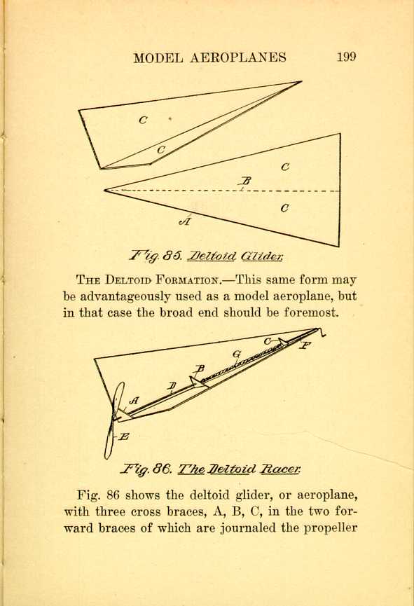
Fig. 85. Deltoid Glider.
[Description: Black and white illustration: a technical diagram.]THE DELTOID FORMATION.—This same form may
be advantageously used as a model aeroplane, but
in that case the broad end should be foremost.

Fig. 86. The Deltoid Racer.
[Description: Black and white illustration: a technical diagram.]
Fig. 86 shows the deltoid glider, or aeroplane, with three cross braces, A, B, C, in the two forward braces of which are journaled the propeller
A short stem F through the rear brace C, provided with a crank, has its inner end connected with the rear end of the shaft D by a rubber band G, by which the propeller is driven.
A tail may be attached to the rear end, or at the apex of the planes, so it can be set for the purpose of directing the angle of flight, but it will be found that this form has remarkable stability in flight, and will move forwardly in a straight line, always making a graceful downward movement when the power is exhausted.
It seems to be a form which has equal stabilizing powers whether at slow or at high speeds, thus differing essentially from many forms which require a certain speed in order to get the best results.
RACING MODELS.—Here and in England many racing models have been made, generally of the A-shaped type, which will be explained hereinafter. Such models are also strong, and able to withstand the torsional strain required by the rubber which is used for exerting the power.
It is unfortunate that there is not some type of cheap motor which is light, and adapted to run for several minutes, which would be of great value in work of this kind, but in the absence of such
Unlike the large aeroplanes, the supporting
surfaces, in the models, are at the rear end of
the frames, the pointed ends being in front.
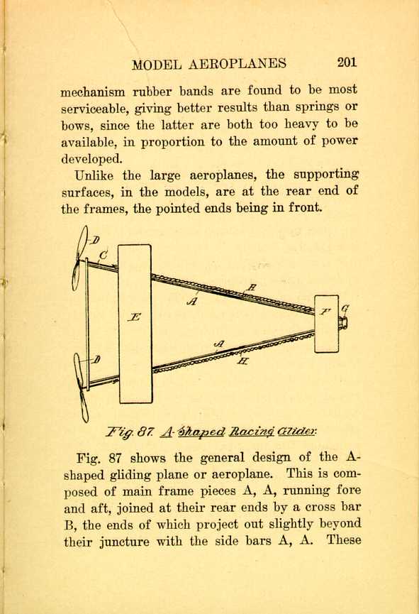
Fig. 87. A-Shaped Racing Glider.
[Description: Black and white illustration: a technical diagram.]
Fig. 87 shows the general design of the A-shaped gliding plane or aeroplane. This is composed of main frame pieces A, A, running fore and aft, joined at their rear ends by a cross bar B, the ends of which project out slightly beyond their juncture with the side bars A, A. These
A main plane E is mounted transversely across this frame at its rear end, while at its forward end is a small plane, called the elevator. The pointed end of the frame has on each side a turnbuckle G, for the purpose of winding up the shaft, and thus twisting the propeller, although this is usually dispensed with, and the propeller itself is turned to give sufficient twist to the rubber for this purpose.
THE POWER FOR MODEL AEROPLANES.—One end of the rubber is attached to the hook of the shaft C, and the other end to the hook or to the turnbuckle G, if it should be so equipped.
The rubbers are twisted in opposite directions, to correspond with the twist of the propeller blades, and when the propellers are permitted to turn, their grip on the air will cause the model to shoot forwardly, until the rubbers are untwisted, when the machine will gradually glide to the ground.
MAKING THE PROPELLER.—These should have the pitch uniform on both ends, and a simple little device can be made to hold the twisted blade after it has been steamed and bent. Birch and holly are good woods for the blades. The strips should be made thin and then boiled, or, what is
They are then taken out and bent by hand, or
secured between a form specially prepared for
the purpose. The device shown in Fig. 88 shows
a base board which has in the center a pair of
parallel pins A, A, slightly separated from each
other.
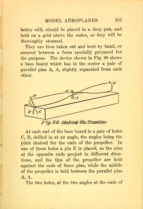
Fig. 88. Making the Propeller.
[Description: Black and white illustration: a technical diagram.]
At each end of the base board is a pair of holes C, D, drilled in at an angle, the angles being the pitch desired for the ends of the propeller. In one of these holes a pin E is placed, so the pins at the opposite ends project in different directions, and the tips of the propeller are held against the ends of these pins, while the middle of the propeller is held between the parallel pins A, A.
The two holes, at the two angles at the ends of
After the twist is made and the blade properly secured in position it should be allowed to thoroughly dry, and afterwards, if it is coated with shellac, will not untwist, as it is the changing character of the atmosphere which usually causes the twisted strips to change their positions. Shellac prevents the moist atmosphere from affecting them.
MATERIAL FOR PROPELLERS.—Very light propellers can also be made of thin, annealed aluminum sheets, and the pins in that case will serve as guides to enable you to get the desired pitch. Fiber board may also be used, but this is more difficult to handle.
Another good material is celluloid sheets, which, when cut into proper strips, is dipped in hot water, for bending purposes, and it readily retains its shape when cooled.
RUBBER—Suitable rubber for the strips are readily obtainable in the market. Experiment will soon show what size and lengths are best adapted for the particular type of propellers which you succeed in making.
PROPELLER SHAPE AND SIZE.—A good proportion
of propeller is shown in Fig. 89. This also
shows the form and manner of connecting the
shaft. The latter A has a hook B on one end to
which the rubber may be attached, and its other
end is flattened, as at C, and secured to the blade
by two-pointed brads D, clinched on the other
side.
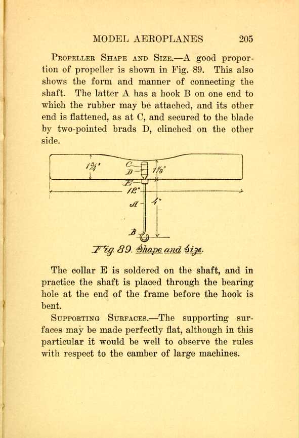
Fig. 89. Shape and Size.
[Description: Black and white illustration: a technical diagram.]
The collar E is soldered on the shaft, and in practice the shaft is placed through the bearing hole at the end of the frame before the hook is bent.
SUPPORTING SURFACES.—The supporting surfaces may be made perfectly flat, although in this particular it would be well to observe the rules with respect to the camber of large machines.
| CHAPTER XIV
EXPERIMENTAL GLIDERS AND MODEL AEROPLANES Aeroplanes | ||