| CHAPTER XI
FLYING MACHINE ACCESSORIES Aeroplanes | ||
11. CHAPTER XI
FLYING MACHINE ACCESSORIES
THE ANEMOMETER.—It requires an expert to judge the force or the speed of a wind, and even they will go astray in their calculations. It is an easy matter to make a little apparatus which will accurately indicate the speed. A device of this kind is called an Anemometer.
Two other instruments have grown out of this, one to indicate the pressure, and the other the direction of the moving air current.
THE ANEMOGRAPH.—While these instruments indicate, they are also made so they will record the speed, the pressure and the direction, and the device for recording the speed and pressure is called a Anemograph.
All these instruments may be attached to the same case, and thus make a handy little device, which will give all the information at a glance.
THE ANEMOMETROGRAPH.—This device for recording, as well as indicating the speed, pressure and direction, is called an Anemometrograph, The two important parts of the combined apparatus,
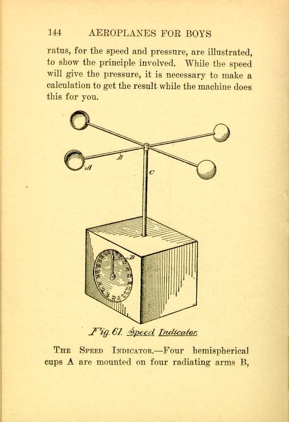
Fig. 61. Speed Indicator.
[Description: Black and white illustration: a technical diagram.]THE SPEED INDICATOR.—Four hemispherical cups A are mounted on four radiating arms B,
On the lower end of the stem C, is a small bevel
pinion, which meshes with a smaller bevel pinion
within the base. This latter is on a shaft which
carries a small gear on its other end, to mesh
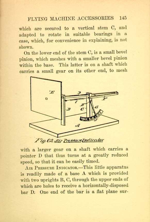
Fig. 62. Air Pressure Indicator.
[Description: Black and white illustration: a technical diagram.]
AIR PRESSURE INDICATOR.—This little apparatus is readily made of a base A which is provided with two uprights B, C, through the upper ends of which are holes to receive a horizontally-disposed bar D. One end of the bar is a flat plane surface
The other end of the bar has a lateral pin to serve as a pivot for the end of a link F, its other end being hinged to the upper end of a lever G, which is pivoted to the post C, a short distance below the hinged attachment of the link F, so that the long end of the pointer which is constituted by the lever G is below its pivot, and has, therefore, a long range of movement.
A spring I between the upper end of the pointer G and the other post B, serves to hold the pointer at a zero position. A graduated scale plate J, within range of the pointer will show at a glance the pressure in pounds of the moving wind, and for this purpose it would be convenient to make the plane E exactly one foot square.
DETERMINING THE PRESSURE FROM THE SPEED.—These two instruments can be made to check each other and thus pretty accurately enable you to determine the proper places to mark the pressure indicator, as well as to make the wheels in the anemometer the proper size to turn the pointer in seconds when the wind is blowing at a certain speed, say ten miles per hour.
Suppose the air pressure indicator has the scale divided into quarter pound marks. This will make it accurate enough for all purposes.
CALCULATING PRESSURES FROM SPEED.—The following table will give the pressures from 5 to 100 miles per hour:
| Velocity of wind in | Pressure | Velocity of wind in | Pressure | |
| miles per hour | per sq. ft. | miles per hour | per sq ft | |
| 5 | .112 | 55 | 15.125 | |
| 10 | .500 | 60 | 18.000 | |
| 15 | 1.125 | 65 | 21.125 | |
| 20 | 2.000 | 70 | 22.500 | |
| 25 | 3.125 | 75 | 28.125 | |
| 30 | 4.600 | 80 | 32.000 | |
| 35 | 6.126 | 86 | 36.126 | |
| 40 | 8.000 | 90 | 40.500 | |
| 45 | 10.125 | 95 | 45.125 | |
| 50 | 12.5 | 100 | 50.000 |
HOW THE FIGURES ARE DETERMINED.—The foregoing figures are determined in the following manner: As an example let us assume that the velocity of the wind is forty-five miles per hour. If this is squared, or 45 multiplied by 45, the product is 2025. In many calculations the mathematician employs what is called a constant, a figure that never varies, and which is used to multiply or divide certain factors.
In this case the constant is 5/1000, or, as usually written, .005. This is the same as one two hundredths of the squared figure. That would make the problem as follows:
45 X 45 = 2025 200 = 10.125; or,
45 X 45 -2025 X .005 = 10.125.
Again, twenty-five miles per hour would be 25 X 25 = 625; and this multiplied by .005 equals 2 pounds pressure.
CONVERTING HOURS INTO MINUTES.—It is sometimes confusing to think of miles per hour, when you wish to express it in minutes or seconds. A simple rule, which is not absolutely accurate, but is correct within a few feet, in order to express the speed in feet per minute, is to multiply the figure indicating the miles per hour, by 8 3/4.
To illustrate: If the wind is moving at the rate of twenty miles an hour, it will travel in that time 105,600 feet (5280 X 20). As there are sixty minutes in an hour, 105,600 divided by 60, equals 1760 feet per minute. Instead of going through all this process of calculating the speed per minute, remember to multiply the speed in miles per hour by 90, which will give 1800 feet.
This is a little more then two per cent. above the correct figure. Again; 40 X 90 equals 3600. As the correct figure is 3520, a little mental calculation will enable you to correct the figures so as to get it within a few feet.
CHANGING SPEED HOURS TO SECONDS.—As one-sixtieth of the speed per minute will represent the rate of movement per second, it is a comparatively
As examples, take the following: If the wind is traveling 20 miles an hour, it is easy to take one-half of 20, which is 10, and add it to 20, making 30, as the number of feet per second. If the wind travels 50 miles per hour, add 25, making 75, as the speed per second.
The correct speed per second of a wind traveling 20 miles an hour is a little over 29 feet. At 50 miles per hour, the correct figure is 73 1/3 feet, which show that the figures under this rule are within about one per cent. of being correct.
With the table before you it will be an easy matter, by observing the air pressure indicator, to determine the proper speed for the anemometer. Suppose it shows a pressure of two pounds, which will indicate a speed of twenty miles an hour. You have thus a fixed point to start from.
PRESSURE AS THE SQUARE OF THE SPEED.—Now it must not be assumed that if the pressure at twenty miles an hour is two pounds, that forty miles an hour it is four pounds. The pressure is as the square of the speed. This may be explained as follows: As the speed of the wind increases,
As an example of this, let us take a speed of ten miles an hour, which means a pressure of one-half pound. Double this speed, and we have 20 miles. Multiplying one-half pound by 4, the result is 2 pounds. Again, double 20, which means 40 miles, and multiplying 2 by 4, the result is 8. Doubling forty is eighty miles an hour, and again multiplying 8 by 4, we have 32 as the pounds pressure at a speed of 80 miles an hour.
The anemometer, however, is constant in its speed. If the pointer should turn once a second at 10 miles an hour, it would turn twice at 20 miles an hour, and four times a second at 40 miles an hour.
GYROSCOPIC BALANCE.—Some advance has been made in the use of the gyroscope for the purpose of giving lateral stability to an aeroplane. While the best of such devices is at best a makeshift, it is well to understand the principle on which they operate, and to get an understanding how they are applied.
THE PRINCIPLE INVOLVED.—The only thing known about the gyroscope is, that it objects to
To explain this without being too technical, examine
Fig. 63, which shows a gyroscopic top, one
end of the rim A, which supports the rotating
wheel B, having a projecting finger C, that is
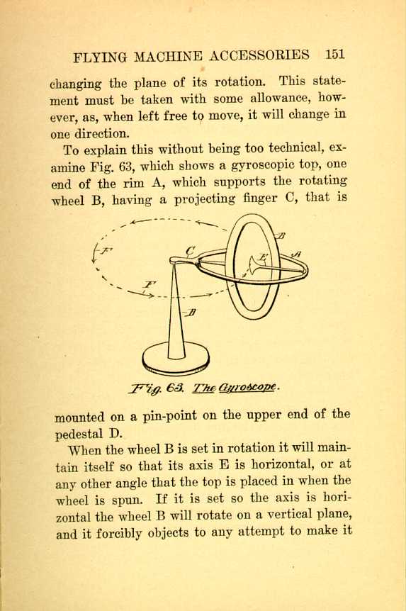
Fig. 63. The Gyroscope.
[Description: Black and white illustration: a technical diagram.]
When the wheel B is set in rotation it will maintain itself so that its axis E is horizontal, or at any other angle that the top is placed in when the wheel is spun. If it is set so the axis is horizontal the wheel B will rotate on a vertical plane, and it forcibly objects to any attempt to make it
The wheel B will cause the axis E to swing
around on a horizontal plane, and this turning
movement is always in a certain direction in relation
to the turn of the wheel B, and it is obvious,
therefore, that to make a gyroscope that
will not move, or swing around an axis, the placing
of two such wheels side by side, and rotated
in opposite directions, will maintain them in a
fixed position; this can also be accomplished by
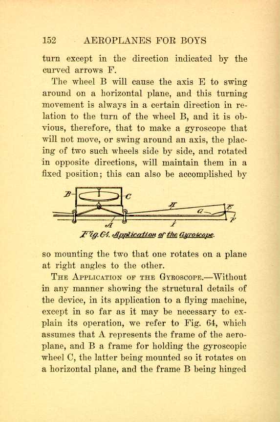
Fig. 64. Application of the Gyroscope.
[Description: Black and white illustration: a technical diagram.]
THE APPLICATION OF THE GYROSCOPE.—Without in any manner showing the structural details of the device, in its application to a flying machine, except in so far as it may be necessary to explain its operation, we refer to Fig. 64, which assumes that A represents the frame of the aeroplane, and B a frame for holding the gyroscopic wheel C, the latter being mounted so it rotates on a horizontal plane, and the frame B being hinged
For convenience in explaining the action, the
planes E are placed at right angles to their regular
positions, F being the forward margin of the
plane, and G the rear edge. Wires H connect
the ends of the frame B with the respective
planes, or ailerons, E, and another wire I joins
the downwardly-projecting arms of the two
ailerons, so that motion is transmitted to both at
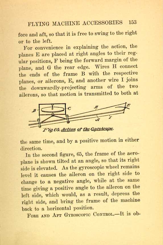
Fig. 65. Action of the Gyroscope.
[Description: Black and white illustration: a technical diagram.]
In the second figure, 65, the frame of the aeroplane is shown tilted at an angle, so that its right side is elevated. As the gyroscopic wheel remains level it causes the aileron on the right side to change to a negative angle, while at the same time giving a positive angle to the aileron on the left side, which would, as a result, depress the right side, and bring the frame of the machine back to a horizontal position.
FORE AND AFT GYROSCOPIC CONTROL.—It is obvious
Laterally the ship should not be out of balance; fore and aft this is a necessity, and as the great trouble with all aeroplanes is to control them laterally, it may well be doubted whether it would add anything of value to the machine by having an automatic fore and aft control, which might, in emergencies, counteract the personal control of the operator.
ANGLE INDICATOR.—In flight it is an exceedingly difficult matter for the pilot to give an accurate idea of the angle of the planes. If the air is calm and he is moving over a certain course, and knows, from experience, what his speed is, he may be able to judge of this factor, but he cannot tell what changes take place under certain conditions during the flight.
For this purpose a simple little indicator may be provided, shown in Fig. 66, which is merely a vertical board A, with a pendulum B, swinging fore and aft from a pin a which projects out from the board a short distance above its center.
The upper end of the pendulum has a heart-shaped wire structure D, that carries a sliding
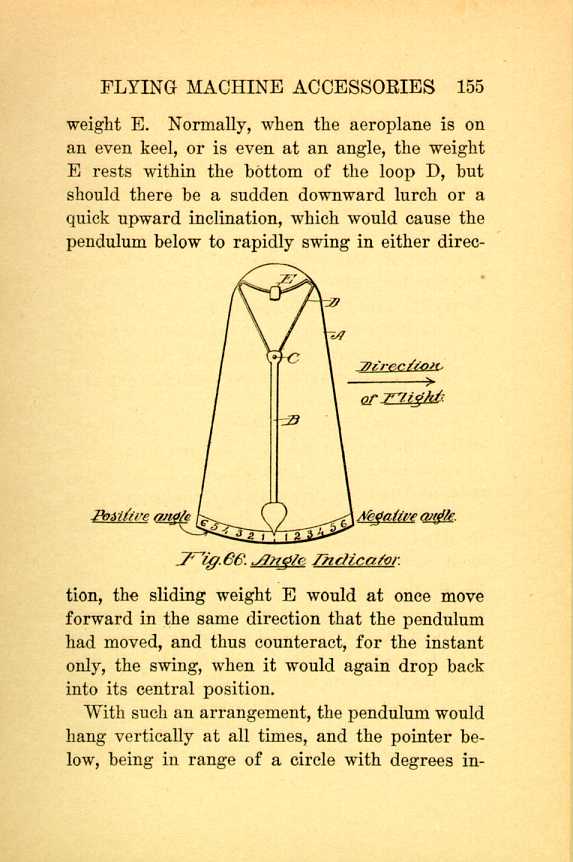
Fig. 66. Angle Indicator.
[Description: Black and white illustration: a technical diagram.]With such an arrangement, the pendulum would hang vertically at all times, and the pointer below, being in range of a circle with degrees indicated
PENDULUM STABILIZER.—In many respects the
use of a pendulum has advantages over the gyroscope.
The latter requires power to keep it in
motion. The pendulum is always in condition
for service. While it may be more difficult to
adjust the pendulum, so that it does not affect
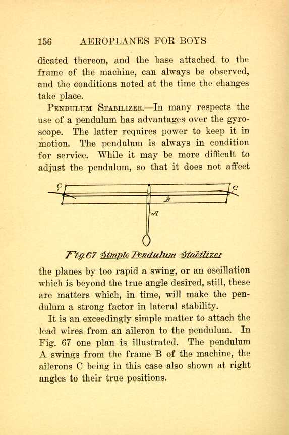
Fig. 67. Simple Pendulum Stabilizer.
[Description: Black and white illustration: a technical diagram.]
It is an exceedingly simple matter to attach the lead wires from an aileron to the pendulum. In Fig. 67 one plan is illustrated. The pendulum A swings from the frame B of the machine, the ailerons a being in this case also shown at right angles to their true positions.
The other, Fig. 68, assumes that the machine is exactly horizontal, and as the pendulum is in a vertical position, the forward edges of both ailerons are elevated, but when the pendulum swings both ailerons will be swung with their forward margins up or down in unison, and thus the proper angles are made to right the machine.
STEERING AND CONTROLLING WHEEL.—For the
purpose of concentrating the control in a single
wheel, which has not alone a turning motion, but
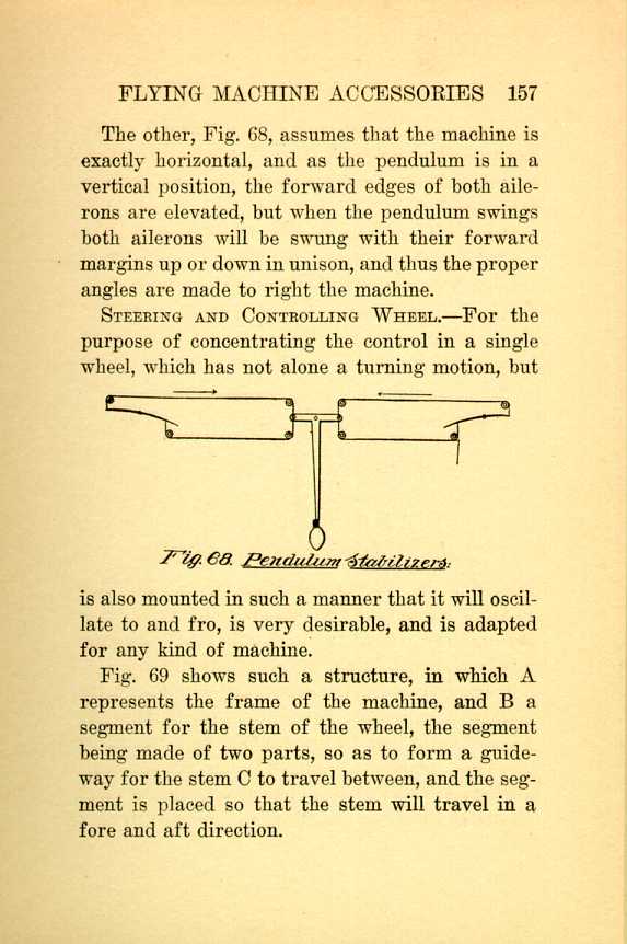
Fig. 68. Pendulum Stabilizers.
[Description: Black and white illustration: a technical diagram.]
Fig. 69 shows such a structure, in which A represents the frame of the machine, and B a segment for the stem of the wheel, the segment being made of two parts, so as to form a guideway for the stem a to travel between, and the segment is placed so that the stem will travel in a fore and aft direction.
The lower end of the stem is mounted in a
socket, at D, so that while it may be turned, it
will also permit this oscillating motion. Near its
lower end is a cross bar E from which the wires
run to the vertical control plane, and also to the
ailerons, if the machine is equipped with them, or
to the warping ends of the planes.
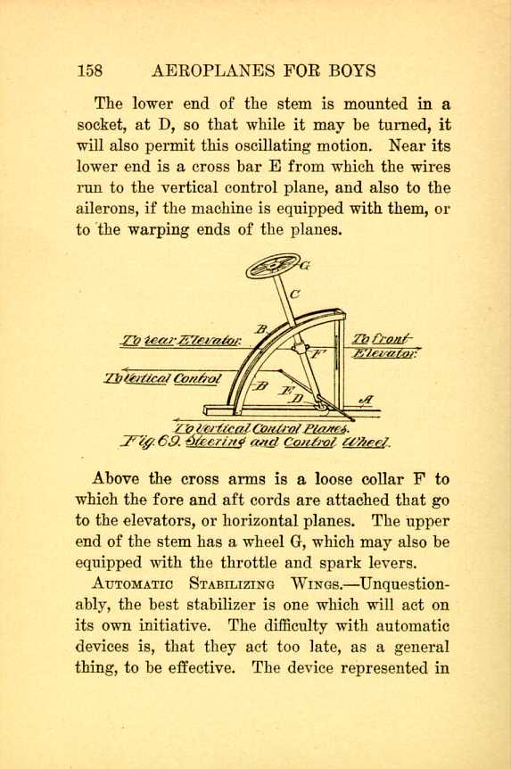
Fig. 69. Steering and Control Wheel.
[Description: Black and white illustration: a technical diagram.]
Above the cross arms is a loose collar F to which the fore and aft cords are attached that go to the elevators, or horizontal planes. The upper end of the stem has a wheel G, which may also be equipped with the throttle and spark levers.
AUTOMATIC STABILIZING WINGS.—Unquestionably, the best stabilizer is one which will act on its own initiative. The difficulty with automatic devices is, that they act too late, as a general thing, to be effective. The device represented in
In this Fig. 70 A and B represent the upper
and the lower planes, respectively. Near the end
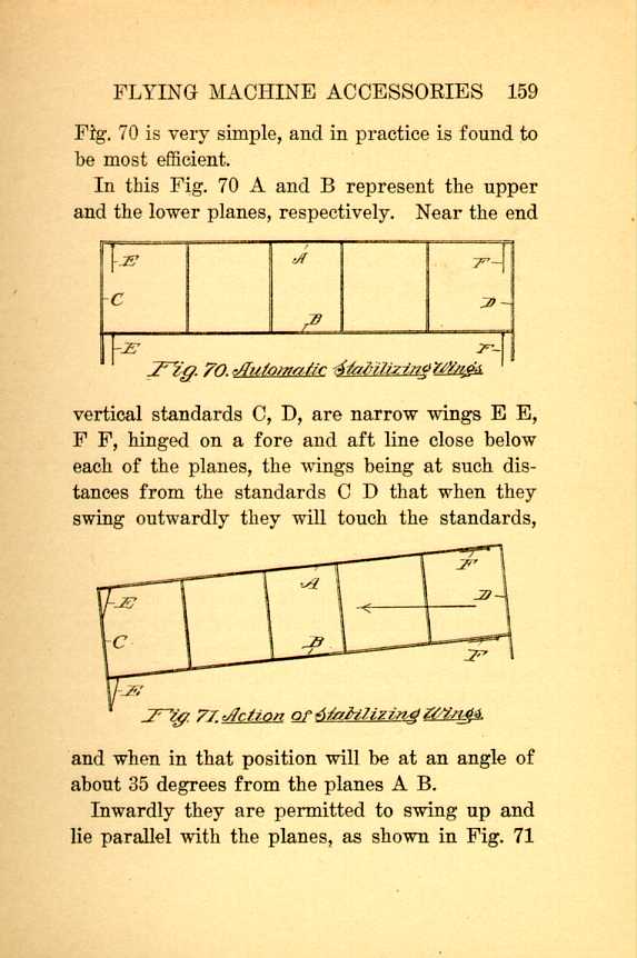
Fig. 70. Automatic Stabilizing Wings.
[Description: Black and white illustration: a technical diagram.]

Fig. 71. Action of Stabilizing Wings.
[Description: Black and white illustration: a technical diagram.]
Inwardly they are permitted to swing up and lie parallel with the planes, as shown in Fig. 71
This will be made clear by reference to Fig.
72, in which the dart A represents the direction
of the movement of the aeroplane, and B the direction
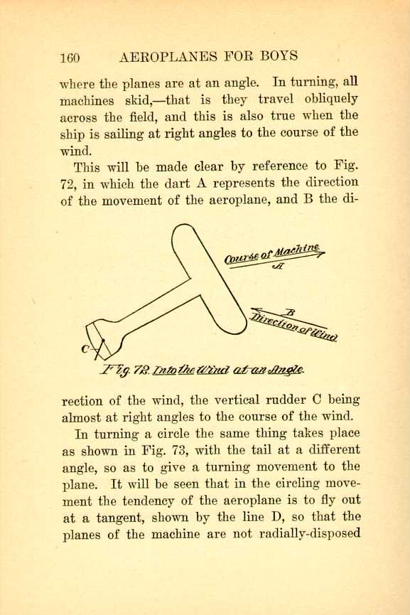
Fig. 72. Into the Wind at an Angle.
[Description: Black and white illustration: a technical diagram.]
In turning a circle the same thing takes place as shown in Fig. 73, with the tail at a different angle, so as to give a turning movement to the plane. It will be seen that in the circling movement the tendency of the aeroplane is to fly out at a tangent, shown by the line D, so that the planes of the machine are not radially-disposed
Referring now to Fig. 71, it will be seen that
this skidding motion of the machine swings the
wings E F inwardly, so that they offer no resistance
to the oblique movement, but the wings E
E, at the other end of the planes are swung outwardly,
to provide an angle, which tends to raise
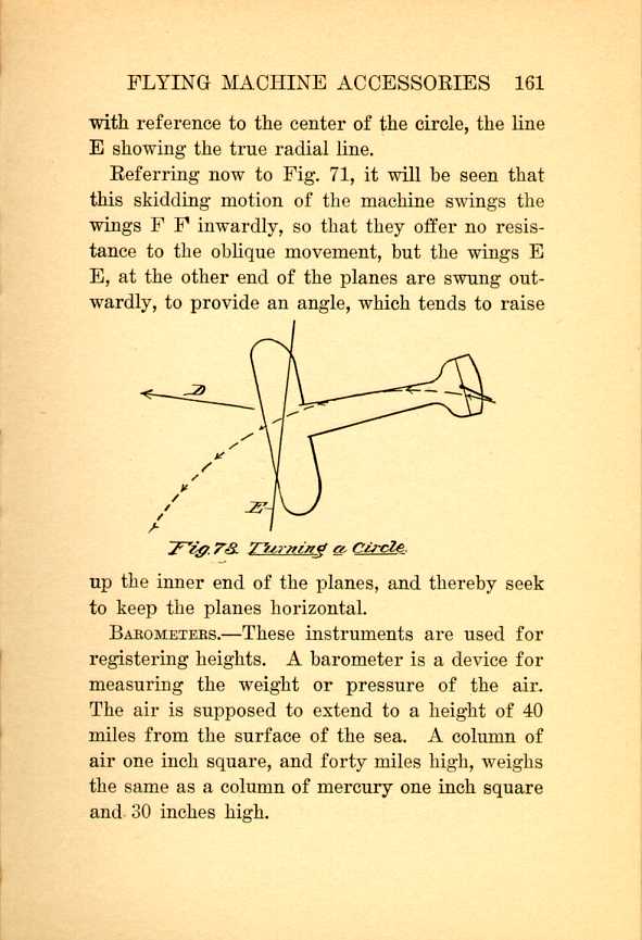
Fig. 73. Turning a Circle.
[Description: Black and white illustration: a technical diagram.]
BAROMETERS.—These instruments are used for registering heights. A barometer is a device for measuring the weight or pressure of the air. The air is supposed to extend to a height of 40 miles from the surface of the sea. A column of air one inch square, and forty miles high, weighs the same as a column of mercury one inch square and 30 inches high
Such a column of air, or of mercury, weighs 14 3/4 pounds. If the air column should be weighed at the top of the mountain, that part above would weigh less than if measured at the sea level, hence, as we ascend or descend the pressure becomes less or more, dependent on the altitude.
Mercury is also used to indicate temperature,
but this is brought about by the expansive quality
of the mercury, and not by its weight.
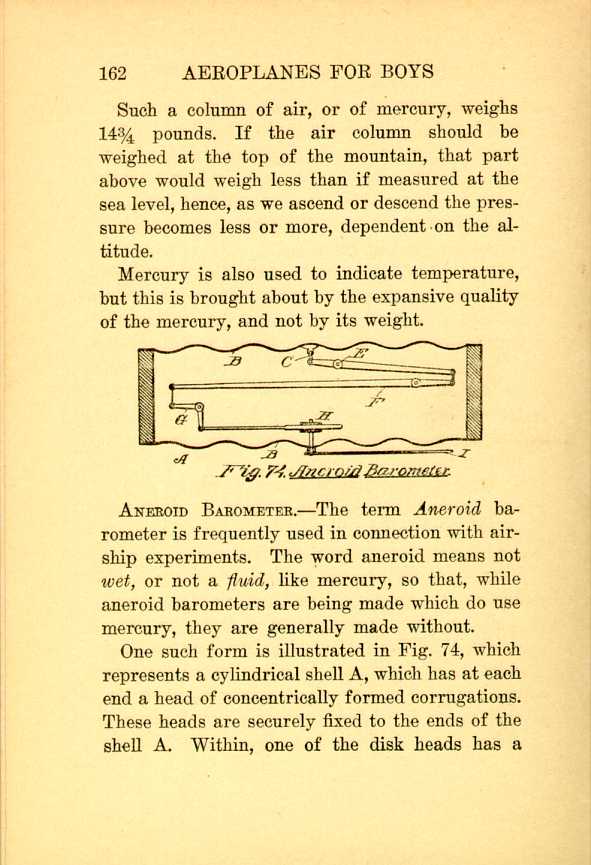
Fig. 74. Aneroid Barometer.
[Description: Black and white illustration: a technical diagram.]
ANEROID BAROMETER.—The term Aneroid barometer is frequently used in connection with air-ship experiments. The word aneroid means not wet, or not a fluid, like mercury, so that, while aneroid barometers are being made which do use mercury, they are generally made without.
One such form is illustrated in Fig. 74, which represents a cylindrical shell A, which has at each end a head of concentrically formed corrugations. These heads are securely fixed to the ends of the shell A. Within, one of the disk heads has a
This end of the lever F connects with one limb of a bell-crank lever G, and its other limb has a toothed rack connection with a gear H, which turns the shaft to which the pointer I is attached.
Air is withdrawn from the interior of the shell, so that any change in the pressure, or weight of the atmosphere, is at once felt by the disk heads, and the finger turns to indicate the amount of pressure.
HYDROPLANES.—Hydro means water, hence the term hydroplane has been given to machines which have suitable pontoons or boats, so they may alight or initiate flight from water.
There is no particular form which has been adopted to attach to aeroplanes, the object generally being to so make them that they will sustain the greatest amount of weight with the least submergence, and also offer the least resistance while the motor is drawing the machine along the surface of the water, preparatory to launching it.
SUSTAINING WEIGHT OF PONTOONS.—A pontoon
It is, therefore, an easy matter to determine how much of solid matter will be sustained by a pontoon of a given size, or what the dimensions of a pontoon should be to hold up an aeroplane which weighs, with the pilot, say, 1100 pounds.
As we must calculate for a sufficient excess to prevent the pontoons from being too much immersed, and also allow a sufficient difference in weight so that they will keep on the surface when the aeroplane strikes the surface in alighting, we will take the figure of 1500 pounds to make the calculations from.
If this figure is divided by 62½ we shall find the cubical contents of the pontoons, not considering, of course, the weight of the material of which they are composed. This calculation shows that we must have 24 cubic feet in the pontoons.
As there should be two main pontoons, and a smaller one for the rear, each of the main ones might have ten cubic feet, and the smaller one four cubic feet.
SHAPES OF THE PONTOONS.—We are now ready
The type B has a rounded under body, the forward
end being also skiff-shaped to decrease as
much as possible the resistance of the water impact.

Fig. 75. Hydroplane Floats.
[Description: Black and white illustration: a technical diagram.]
The third type C is made in the form of a closed boat, with both ends pointed, and the bottom rounded, or provided with a keel. Or, as in some cases the body may be made triangular in cross section so that as it is submerged its sustaining weight will increase at a greater degree as it is pressed down than its vertical measurement indicates.
All this, however, is a matter left to the judgment of the designer, and is, in a great degree, dependent on the character of the craft to which it is to be applied.
| CHAPTER XI
FLYING MACHINE ACCESSORIES Aeroplanes | ||