| CHAPTER IX
AEROPLANE CONSTRUCTION Aeroplanes | ||
9. CHAPTER IX
AEROPLANE CONSTRUCTION
As may be inferred from the foregoing statements, there are no definite rules for the construction of either type of flying machine, as the flying models vary to such an extent that it is difficult to take either of them as a model to represent the preferred type of construction.
LATERAL, AND FORE AND AFT.—The term lateral should be understood, as applied to aeroplanes. It is always used to designate the direction at right angles to the movement of the machine. Fore and aft is a marine term meaning lengthwise, or from front to rear, hence is always at right angles to the lateral direction.
The term transverse is equivalent to lateral, in flying machine parlance, but there is this distinction: Transverse has reference to a machine or object which, like the main planes of an aeroplane, are broader, (that is,—from end to end) than their length, (from front to rear).
On the other hand, lateral has reference to side branches, as, for instance, the monoplane wings,
STABILITY AND STABILIZATION.—These terms constantly appear in describing machines and their operations. If the flying structure, whatever it may be, has means whereby it is kept from rocking from side to side, it has stability, which is usually designated as lateral stability. The mechanism for doing this is called a stabilizer.
THE WRIGHT SYSTEM.—The Wright machine has reference solely to the matter of laterally controlling the flying structure, and does not pertain to the form or shape of the planes.
In Fig. 49 A designates the upper and lower planes of a Wright machine, with the peculiar rounded ends. The ends of the planes are so arranged that the rear margins may be raised or lowered, independently of the other portions of the planes, which are rigid. This movement is indicated in sketch 1, where the movable part B is, as we might say, hinged along the line C.
The dotted line D on the right hand end, shows how the section is depressed, while the dotted lines E at the left hand end shows the section raised. It is obvious that the downturned ends, as at D, will give a positive angle at one end of the planes, and the upturned wings E at the other end will give a negative angle, and thus cause the right
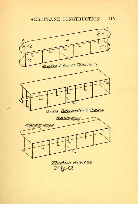
Fig. 49.
[Description: Black and white illustration: a technical diagram.]CONTROLLING THE WARPING ENDS.—Originally the Wrights controlled these warping sections by means of a cradle occupied by the aviator, so that the cradle would move or rock, dependent on the tilt of the machine. This was what was termed automatic control. This was found to be unsatisfactory, and the control has now been placed so that it connects with a lever and is operated by the aviator, and is called Manually-operated control.
In all forms of control the wings on one side are depressed on one side and correspondingly elevated on the other.
THE CURTIS WINGS.—Curtis has small wings, or ailerons, intermediate the supporting surfaces, and at their extremities, as shown in sketch 2. These are controlled by a shoulder rack or swinging frame operated by the driver, so that the body in swinging laterally will change the two wings at the same time, but with angles in different directions.
THE FARMAN AILERONS.—Farman's disposition is somewhat different, as shown in sketch 3. The wings are hinged to the upper planes at their rear edges, and near the extremities of the planes.
The difficulty of using any particular model, is true, also, of the arrangement of the fore and aft control, as well as the means for laterally stabilizing it. In view of this we shall submit a general form, which may be departed from at will.
FEATURES WELL DEVELOPED.—Certain features are fairly well developed, however. One is the angle of the supporting plane, with reference to the frame itself; and the other is the height at which the tail and rudder should be placed above the surface of the ground when the machine is at rest.
DEPRESSING THE REAR END.—This latter is a matter which must be taken into consideration, because in initiating flight the rear end of the frame is depressed in order to give a sufficient angle to the supporting planes so as to be able to inaugurate flight.
In order to commence building we should have some definite idea with respect to the power, as this will, in a measure, determine the area of the supporting surfaces, as a whole, and from this the sizes of the different planes may be determined.
DETERMINING THE SIZE.—Suppose we decide on 300 square feet of sustaining surface. This may
However, let us assume that a forty horse power motor is available, our 300 square feet of surface may be put into two planes, each having 150 square feet of surface, which would make each 5' by 30' in size; or, it may be decided to make the planes narrower, and proportionally longer. This is immaterial. The shorter the planes transversely, the greater will be the stability, and the wider the planes the less will be the lift, comparatively.
RULE FOR PLACING THE PLANES.—The rule for placing the planes is to place them apart a distance equal to the width of the planes themselves, so that if we decide on making them five feet wide, they should be placed at least five feet apart. This rule, while it is an admirable one for slow movements or when starting flight, is not of any advantage while in rapid flight.
If the machine is made with front and rear horizontally-disposed rudders, or elevators, they also serve as sustaining surfaces, which, for the present will be disregarded.
Lay off a square A, Fig. 49a, in which the vertical lines B, B, and the horizontal lines C, C, are 5' long, and draw a cross D within this, the lines running diagonally from the corners.
Now step off from the center cross line D, three
spaces, each five feet long, to a point E, and join
this point by means of upper and lower bars F,
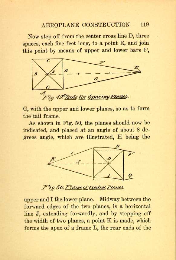
Fig. 49a. Rule for spacing Planes.
[Description: Black and white illustration: a technical diagram.]
As shown in Fig. 50, the planes should now be
indicated, and placed at an angle of about 8 degrees
angle, which are illustrated, H being the
Fig. 50. Frame of Control Planes.
[Description: Black and white illustration: a technical diagram.]
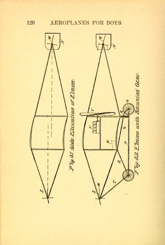
Fig. 51. [and] Fig. 52.
[Description: Black and white illustration: a technical diagram.]ELEVATING PLANES.—We must now have the general side elevation of the frame, the planes, their angles, the tail and the rudder support, and the frame for the forward elevator.
To this may be added the forward elevating plane L, the rear elevator, or tail M, and the vertical steering rudder N.
The frame which supports the structure thus described, may be made in a variety of ways, the object being to provide a resilient connection for the rear wheel O.
Fig. 52 shows a frame which is simple in construction and easily attached. The lower fore and aft side bars P have the single front wheel axle at the forward end, and the aft double wheels at the rear end, a flexible bar Q, running from the rear wheel axle to the forward end of the lower plane.
A compression spring R is also mounted between the bar and rear end of the lower plane to take the shock of landing. The forward end of the bar P has a brace S extending up to the front edge of the lower plane, and another brace T connects the bars P, S, with the end of the forwardly-projecting frame.
The full page view, Fig. 53, represents a plan
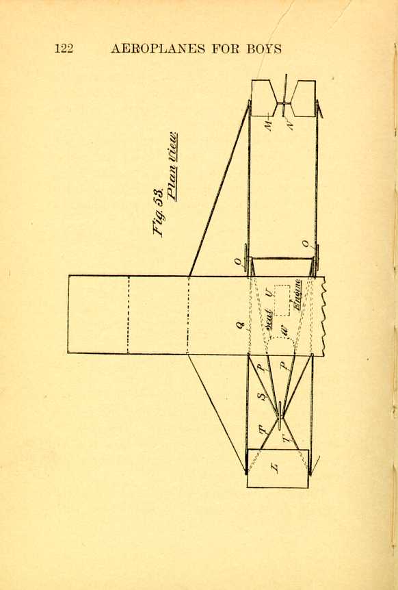
Fig. 53. Plan view.
[Description: Black and white illustration: a technical diagram.]The necessity of the rear end elevation will
now be referred to. The tail need not, necessarily,
be located at a point on a horizontal line
between the planes. It may be higher, or lower
than the planes, but it should not be in a position
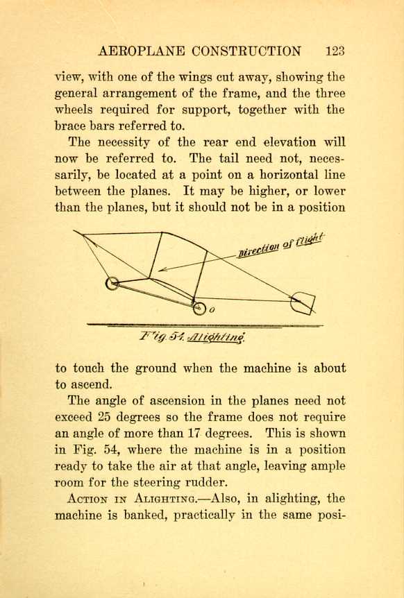
Fig. 54. Alighting.
[Description: Black and white illustration: a technical diagram.]
The angle of ascension in the planes need not exceed 25 degrees so the frame does not require an angle of more than 17 degrees. This is shown in Fig. 54, where the machine is in a position ready to take the air at that angle, leaving ample room for the steering rudder.
ACTION IN ALIGHTING.—Also, in alighting, the machine is banked, practically in the same position
The motor U is usually mounted so its shaft is midway between the planes, the propeller V being connected directly with the shaft, and being behind the planes, is on a medial line with the machine.
The control planes L, M, N, are all connected up by means of flexible wires with the aviator at the set W, the attachments being of such a character that their arrangement will readily suggest themselves to the novice.
THE MONOPLANE.—From a spectacular standpoint a monoplane is the ideal flying machine. It is graceful in outline, and from the fact that it closely approaches the form of the natural flyer, seems to be best adapted as a type, compared with the biplane.
THE COMMON FLY.—So many birds have been cited in support of the various flying theories that the house fly, as an example has been disregarded. We are prone to overlook the small insect, but it is, nevertheless, a sample which is just as potent to show the efficiency of wing surface as the condor or the vulture.
The fly has greater mobility than any other flying creature. By the combined action of its legs and wings it can spring eighteen inches in the
If a sparrow had the same dexterity, proportionally,
it could make a flight of 800 feet in the
same time. The posterior legs of the fly are the
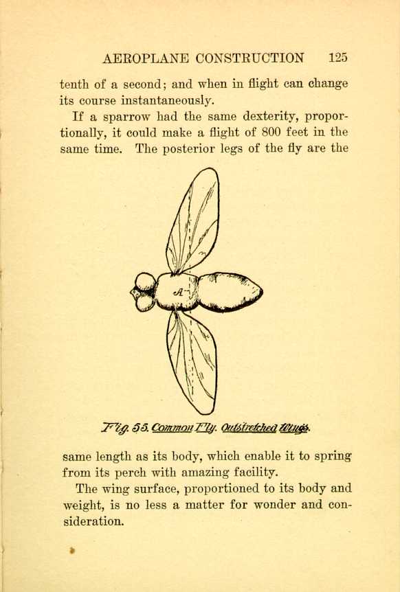
Fig. 55. Common Fly. Outstretched Wings.
[Description: Black and white illustration: a technical diagram.]
The wing surface, proportioned to its body and weight, is no less a matter for wonder and consideration.
In Fig. 55 is shown the outlines of the fly with
outstretched wings. Fig. 56 represents it with
the wing folded, and Fig. 57 is a view of a wing
with the relative size of the top of the body shown
in dotted lines.

Fig. 56. Common Fly. Folded Wings.
[Description: Black and white illustration: a technical diagram.]
The first thing that must attract attention, after
a careful study is the relative size of the body
and wing surface. Each wing is slightly smaller
than the upper surface of the body, and the thickness
of the body is equal to each wing spread.
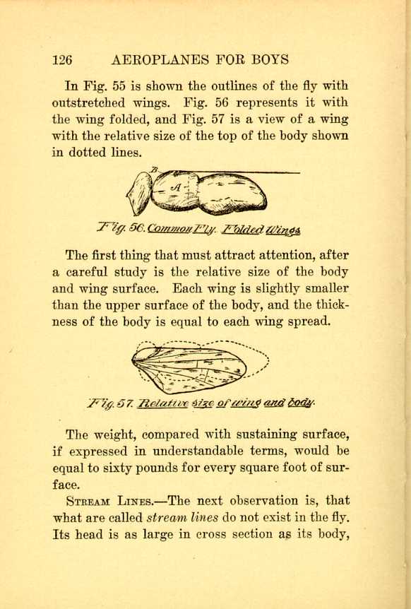
Fig. 57. Relative size of wing and body.
[Description: Black and white illustration: a technical diagram.]
The weight, compared with sustaining surface, if expressed in understandable terms, would be equal to sixty pounds for every square foot of surface.
STREAM LINES.—The next observation is, that what are called stream lines do not exist in the fly. Its head is as large in cross section as its body,
It will also be observed that the wing connection with the body is forward of the line A, which represents the point at which the body will balance itself, and this line passes through the wings so that there is an equal amount of supporting surface fore and aft of the line.
Again, the wing attachment is at the upper side of the body, and the vertical dimension of the body, or its thickness, is equal to four-fifths of the length of he wing.
The wing socket permits a motion similar to a universal joint, Fig. 55 showing how the inner end of the wing has a downward bend where it joins the back, as at B.
THE MONOPLANE FORM.—For the purpose of making comparisons the illustrations of the monoplane show a machine of 300 square feet of surface, which necessitates a wing spread of forty feet from tip to tip, so that the general dimensions of each should be 18½ feet by 8½ feet at its widest point.
First draw a square forty feet each way, as in
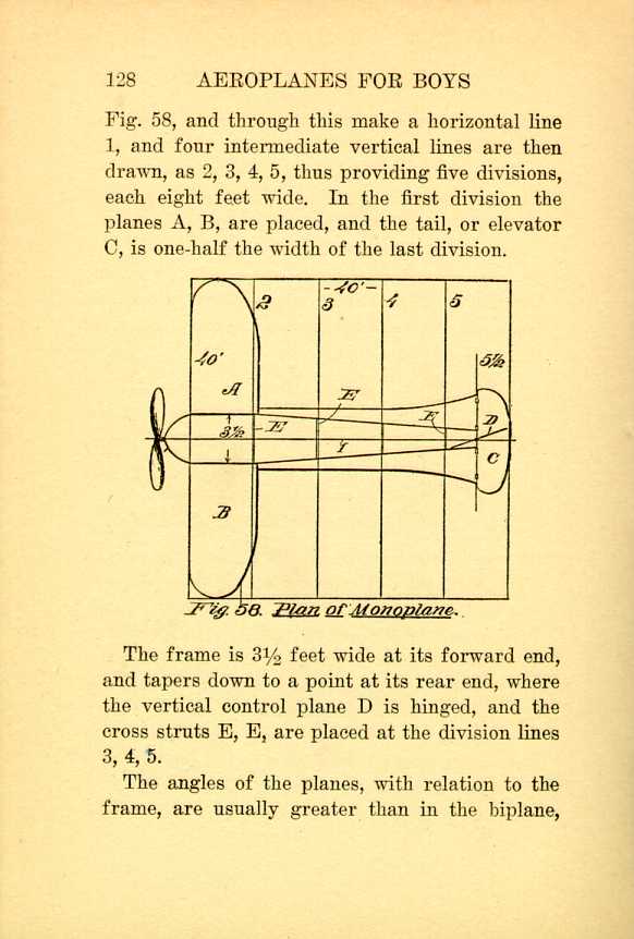
Fig. 58. Plan of Monoplane.
[Description: Black and white illustration: a technical diagram.]The frame is 3½ feet wide at its forward end, and tapers down to a point at its rear end, where the vertical control plane D is hinged, and the cross struts E, E, are placed at the division lines 3, 4, 5.
The angles of the planes, with relation to the frame, are usually greater than in the biplane,
Some monoplanes are built so they have a support
on wheels placed fore and aft. In others
the tail is supported by curved skids, as shown
at A, Fig. 59, in which case the forward supporting
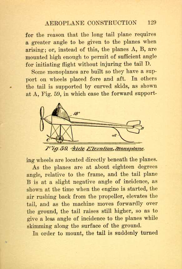
Fig. 59. Side Elevation, Monoplane.
[Description: Black and white illustration: a technical diagram.]
In order to mount, the tail is suddenly turned
The drawing shows a skid at the forward end, attached to the frame which carries the wheels. The wheels are mounted beneath springs so that when the machine alights the springs yield sufficiently to permit the skids to strike the ground, and they, therefore, act as brakes, to prevent the machine from traveling too far.
| CHAPTER IX
AEROPLANE CONSTRUCTION Aeroplanes | ||