| CHAPTER IV
FORE AND AFT CONTROL Aeroplanes | ||
4. CHAPTER IV
FORE AND AFT CONTROL
THERE is no phase of the art of flying more important than the fore and aft control of an airship. Lateral stability is secondary to this feature, for reasons which will appear as we develop the subject.
THE BIRD TYPE OF FORE AND AFT CONTROL.—Every aeroplane follows the type set by nature in the particular that the body is caused to oscillate on a vertical fore and aft plane while in flight. The bird has one important advantage, however, in structure. Its wing has a flexure at the joint, so that its body can so oscillate independently of the angle of the wings.
The aeroplane has the wing firmly fixed to the body, hence the only way in which it is possible to effect a change in the angle of the wing is by changing the angle of the body. To be consistent the aeroplane should be so constructed that the angle of the supporting surfaces should be movable, and not controllable by the body.
The bird, in initiating flight from a perch, darts
ANGLE AND DIRECTION OF FLIGHT.—In order to become familiar with terms which will be frequently used throughout the book, care should be taken to distinguish between the terms angle and direction of flight. The former has reference to the up and down movement of an aeroplane, whereas the latter is used to designate a turning movement to the right or to the left.
WHY SHOULD THE ANGLE OF THE BODY CHANGE?—The first question that presents itself is, why should the angle of the aeroplane body change? Why should it be made to dart up and down and produce a sinuous motion? Why should its nose tilt toward the earth, when it is descending, and raise the forward part of the structure while ascending?
The ready answer on the part of the bird-form advocate is, that nature has so designed a flying structure. The argument is not consistent, because in this respect, as in every other, it is not made to conform to the structure which they seek to copy.
CHANGING ANGLE OF BODY NOT SAFE.—Furthermore,
there is not a single argument which can be
advanced in behalf of that method of building,
which proves it to be correct. Contrariwise, an
analysis of the flying movement will show that it is
the one feature which has militated against safety,
and that machines will never be safe so long as
the angle of the body must be depended upon to
control the angle of flying.
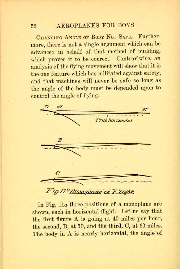
Fig. 11a Monoplane in Flight.
[Description: Black and white illustration: a technical diagram.]
In Fig. 11a three positions of a monoplane are shown, each in horizontal flight. Let us say that the first figure A is going at 40 miles per hour, the second, B, at 50, and the third, C, at 60 miles. The body in A is nearly horizontal, the angle of
When the speed increases to 50 miles an hour,
the angle of incidence in the plane D must be
decreased, so that the rear end of the frame must
be raised, which is done by giving the tail an angle
of incidence, otherwise, as the upper side of the
tail should meet the air it would drive the rear
end of the frame down, and thus defeat the attempt
to elevate that part.
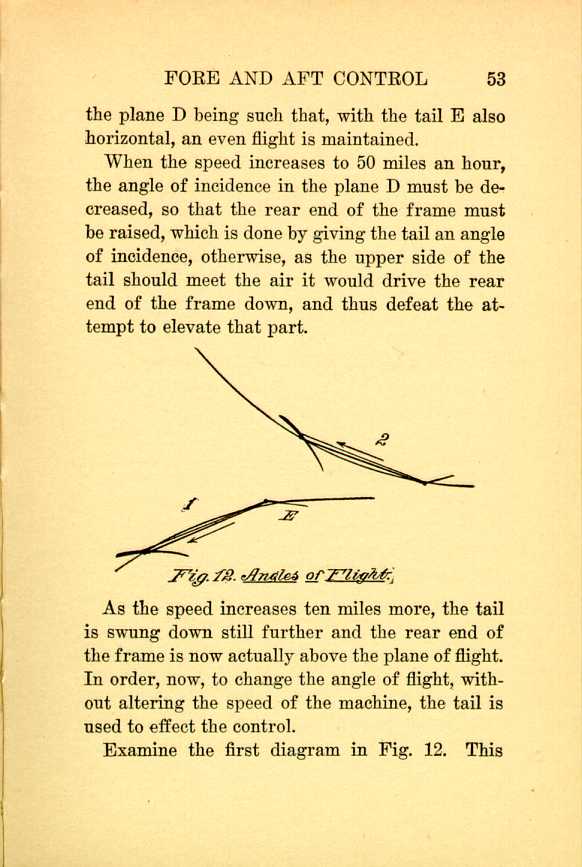
Fig. 12. Angles of Flight.
[Description: Black and white illustration: a technical diagram.]
As the speed increases ten miles more, the tail is swung down still further and the rear end of the frame is now actually above the plane of flight. In order, now, to change the angle of flight, without altering the speed of the machine, the tail is used to effect the control.
Examine the first diagram in Fig. 12. This
In order to ascend, the tail, as shown in the second diagram, is elevated so as to depress the rear end, and now the sustaining surface shoots upwardly.
Suppose that in either of the positions 1 or 2, thus described, the aviator should lose control of the mechanism, or it should become deranged or "stick," conditions which have existed in the history of the art, what is there to prevent an accident?
In the first case, if there is room, the machine will loop the loop, and in the second case the machine will move upwardly until it is vertical, and then, in all probability, as its propelling power is not sufficient to hold it in that position, like a helicopter, and having absolutely no wing supporting surface when in that position, it will dart down tail foremost.
A NON-CHANGING BODY.—We may contrast the foregoing instances of flight with a machine having the sustaining planes hinged to the body in such a manner as to make the disposition of its
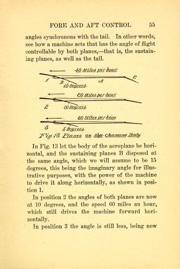
Fig. 13. Planes on Non-changing Body.
[Description: Black and white illustration: a technical diagram.]In Fig. 13 let the body of the aeroplane be horizontal, and the sustaining planes B disposed at the same angle, which we will assume to be 15 degrees, this being the imaginary angle for illustrative purposes, with the power of the machine to drive it along horizontally, as shown in position 1.
In position 2 the angles of both planes are now at 10 degrees, and the speed 60 miles an hour, which still drives the machine forward horizontally.
In position 3 the angle is still less, being now
Now it is obvious that in order to ascend, in
either case, the changing of the planes to a greater
angle would raise the machine, but at the same
time keep the body on an even keel.
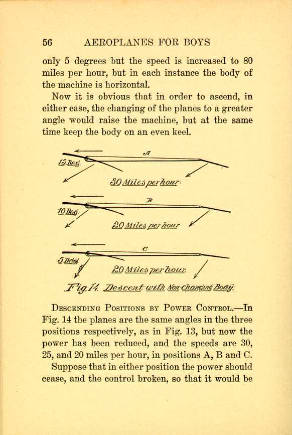
Fig. 14. Descent with Non-changing Body.
[Description: Black and white illustration: a technical diagram.]
DESCENDING POSITIONS BY POWER CONTROL.—In Fig. 14 the planes are the same angles in the three positions respectively, as in Fig. 13, but now the power has been reduced, and the speeds are 30, 25, and 20 miles per hour, in positions A, B and C.
Suppose that in either position the power should cease, and the control broken, so that it would be
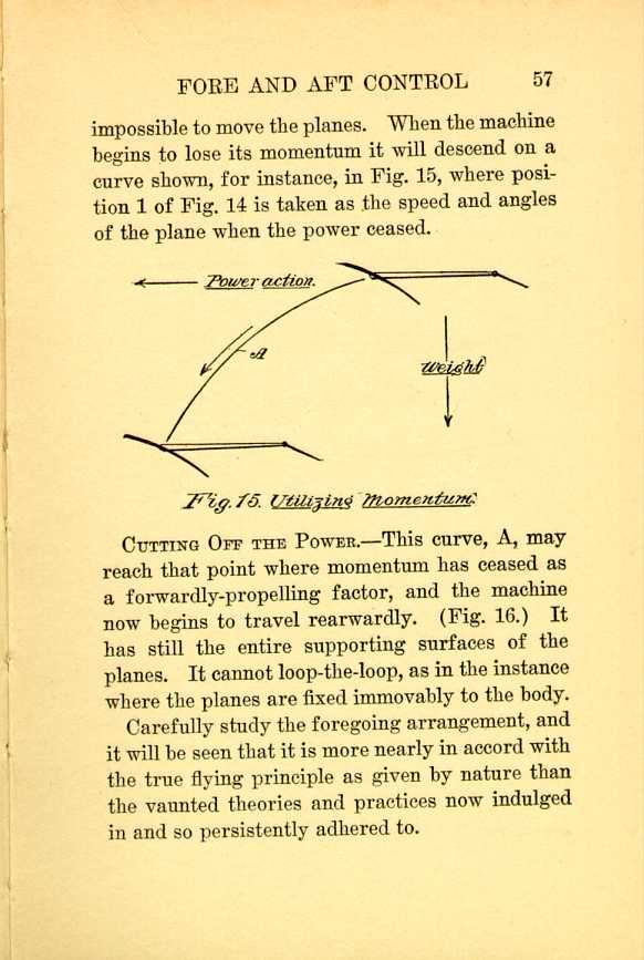
Fig. 15. Utilizing Momentum.
[Description: Black and white illustration: a technical diagram.]CUTTING OFF THE POWER.—This curve, A, may reach that point where momentum has ceased as a forwardly-propelling factor, and the machine now begins to travel rearwardly. (Fig. 16.) It has still the entire supporting surfaces of the planes. It cannot loop-the-loop, as in the instance where the planes are fixed immovably to the body.
Carefully study the foregoing arrangement, and it will be seen that it is more nearly in accord with the true flying principle as given by nature than the vaunted theories and practices now indulged in and so persistently adhered to.
The body of a flying machine should not be oscillated
like a lever. The support of the aeroplane
should never be taken from it. While it may be
impossible to prevent a machine from coming
down, it can be prevented from overturning, and
this can be done without in the least detracting
from it structurally.
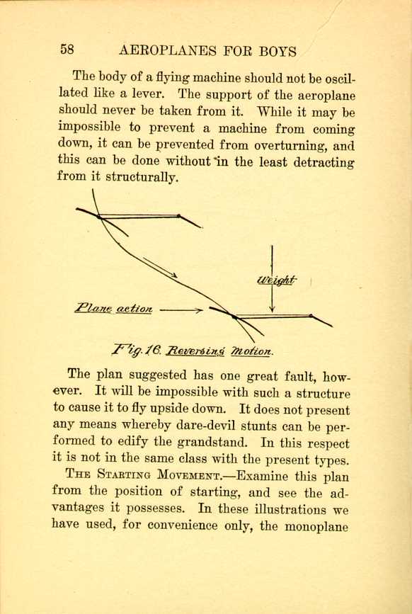
Fig. 16. Reversing Motion.
[Description: Black and white illustration: a technical diagram.]
The plan suggested has one great fault, however. It will be impossible with such a structure to cause it to fly upside down. It does not present any means whereby dare-devil stunts can be performed to edify the grandstand. In this respect it is not in the same class with the present types.
THE STARTING MOVEMENT.—Examine this plan from the position of starting, and see the advantages it possesses. In these illustrations we have used, for convenience only, the monoplane
Fig. 17 shows the starting position of the stock
monoplane, in position 1, while it is being initially
run over the ground, preparatory to launching.
Position 2 represents the negative angle at which
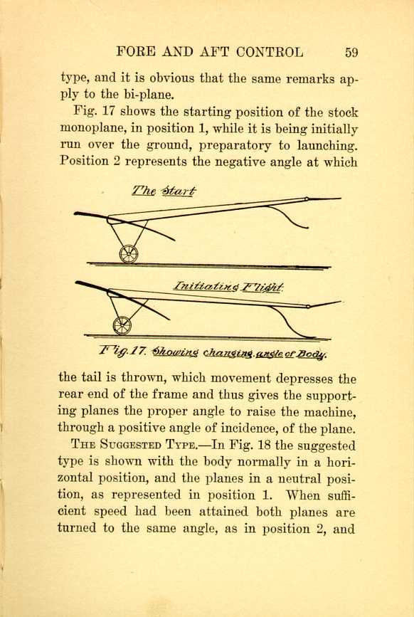
Fig. 17. Showing changing angle of body.
[Description: Black and white illustration: a technical diagram.]
THE SUGGESTED TYPE.—In Fig. 18 the suggested type is shown with the body normally in a horizontal position, and the planes in a neutral position, as represented in position 1. When sufficient speed had been attained both planes are turned to the same angle, as in position 2, and
But now let us see what takes place the moment
the present type is launched. If, by any error on
the part of the aviator, he should fail to readjust
the tail to a neutral or to a proper angle of incidence,
after leaving the ground, the machine would
try to perform an over-head loop.
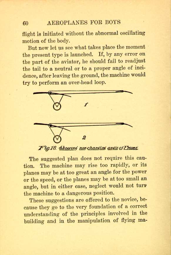
Fig. 18. Showing non-changing angle of Frame.
[Description: Black and white illustration: a technical diagram.]
The suggested plan does not require this caution. The machine may rise too rapidly, or its planes may be at too great an angle for the power or the speed, or the planes may be at too small an angle, but in either case, neglect would not turn the machine to a dangerous position.
These suggestions are offered to the novice, because they go to the very foundation of a correct understanding of the principles involved in the building and in the manipulation of flying machines,
THE LOW CENTER OF GRAVITY.—But we have still
to examine another feature which shows the wrong
principle in the fixed planes. The question is
often asked, why do the builders of aeroplanes
place most of the weight up close to the planes?
It must be obvious to the novice that the lower
the weight the less liability of overturning.
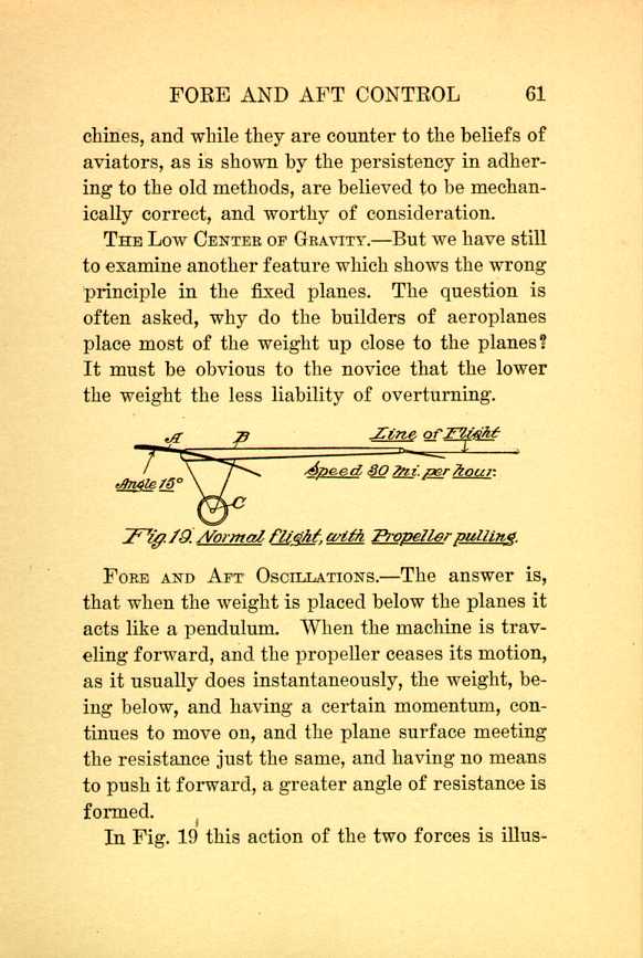
Fig. 19. Normal flight, with Propeller pulling.
[Description: Black and white illustration: a technical diagram.]
FORE AND AFT OSCILLATIONS.—The answer is, that when the weight is placed below the planes it acts like a pendulum. When the machine is traveling forward, and the propeller ceases its motion, as it usually does instantaneously, the weight, being below, and having a certain momentum, continues to move on, and the plane surface meeting the resistance just the same, and having no means to push it forward, a greater angle of resistance is formed.
In Fig. 19 this action of the two forces is illustrated.
The moment the power ceases the weight continues
moving forwardly, and it swings the forward
end of the frame upwardly, Fig. 20, and we now
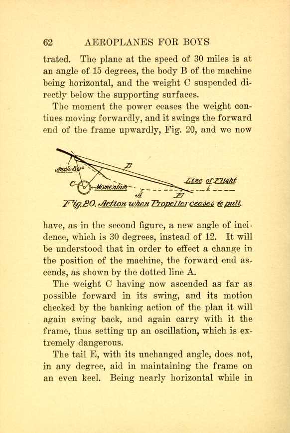
Fig. 20. Action when Propeller ceases to pull.
[Description: Black and white illustration: a technical diagram.]
The weight a having now ascended as far as possible forward in its swing, and its motion checked by the banking action of the plan it will again swing back, and again carry with it the frame, thus setting up an oscillation, which is extremely dangerous.
The tail E, with its unchanged angle, does not, in any degree, aid in maintaining the frame on an even keel. Being nearly horizontal while in
APPLICATION OF THE NEW PRINCIPLE.—Extending the application of the suggested form, let us see wherein it will prevent this pendulous motion at the moment the power ceases to exert a forwardly-propelling force.
In Fig. 21 the body A is shown to be equipped
with the supporting plane B and the tail a, so
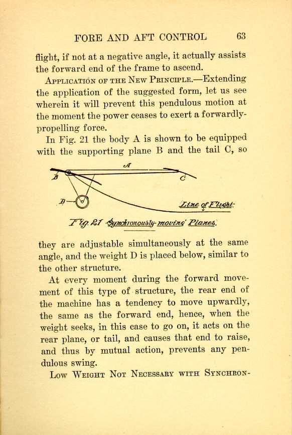
Fig. 21. Synchronously moving Planes.
[Description: Black and white illustration: a technical diagram.]
At every moment during the forward movement of this type of structure, the rear end of the machine has a tendency to move upwardly, the same as the forward end, hence, when the weight seeks, in this case to go on, it acts on the rear plane, or tail, and causes that end to raise, and thus by mutual action, prevents any pendulous swing.
LOW WEIGHT NOT NECESSARY WITH SYNCHRONOUSLY-MOVING
| CHAPTER IV
FORE AND AFT CONTROL Aeroplanes | ||